A device for blowing and spraying powder at the bottom of a ladle in a cyclone-protected gas storage chamber

A cyclone and gas storage technology, applied in the field of iron and steel smelting, can solve the problems that affect the continuous and stable progress of powder spraying smelting, unreasonable design of the gas storage chamber, easy to block the powder air flow delivery pipe, etc. less, good conveying performance

Inactive Publication Date: 2011-12-28
NORTHEASTERN UNIV LIAONING
View PDF7 Cites 4 Cited by
  • Summary
  • Abstract
  • Description
  • Claims
  • Application Information

AI Technical Summary

Problems solved by technology

[0006] (1) The powder impacted on the wall of the gas storage chamber or the powder spraying element falls back and accumulates in the gas storage chamber. When the powder dose accumulates to a certain extent, it is easy to block the powder airflow delivery pipe and affect the normal injection;
[0007] (2) The accumulated powder is lifted up by the main upflow of the powder air flow, resulting in uneven distribution of the powder air flow in the gas storage chamber, and pulsating injection in the form of dense flow. In severe cases, it will block the gap of the refractory material and affect the continuous stability of powder spraying smelting conduct;
[0008] (3) The design of the gas storage chamber is unreasonable, the pressure loss is large, and the kinetic energy of the powder gas injected into the molten pool of the ladle is significantly attenuated

Method used


Image

  • A device for blowing and spraying powder at the bottom of a ladle in a cyclone-protected gas storage chamber
  • A device for blowing and spraying powder at the bottom of a ladle in a cyclone-protected gas storage chamber
  • A device for blowing and spraying powder at the bottom of a ladle in a cyclone-protected gas storage chamber

Examples


Embodiment 1

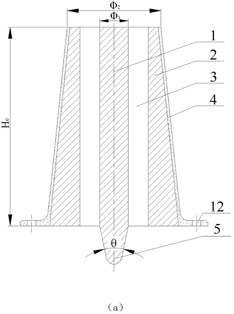
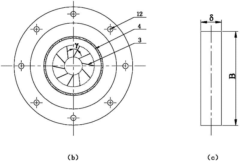
[0035] The refractory material in this embodiment is an air-permeable brick, and its parameters are designed as follows: The structure of the linear slot type powder injection element I is as figure 2 As shown in (a), the main parameters include the inner diameter of ventilated brick core Φ 1 , Outer diameter of breathable brick Φ 2 , Breathable brick height H 0 , Outer cone diversion design cone angle θ, slit size (slit length B and slit width δ), number of slits n and slit layout:

[0036] (1) Brick core inner diameter of breathable brick Φ 1 :The design principle is: not only to avoid too small inner diameter of the brick core to cause the powder airflow to polymerize in the ladle melting pool to form a large bubble cloth bag, but also to avoid the inner diameter of the brick core from being too large, reducing the jet penetration force, and the value of the inner diameter of the brick core Range is Φ 1 =6~300mm, take Φ in this embodiment 1 =15mm;

[0037] (2) Outer diameter of ...

Embodiment 2

[0060] The refractory material in this embodiment is a breathable brick, and its parameters are designed as follows: The structure of the slot type powder spraying element I is as follows: image 3 As shown, the main parameters include the inner diameter of the ventilating brick core Φ 1 , Outer diameter of breathable brick Φ 2 , The distance between adjacent gaps Δd, the height of the breathable brick H 0 , Outer cone diversion design cone angle θ, slit width δ, slit number n and slit layout:

[0061] The specific parameters are designed as follows:

[0062] (1) The inner diameter of the refractory material Φ 1 The value is: to prevent the inner diameter of the brick core from being too small to cause the powder airflow to polymerize in the ladle molten pool to form a large bubble cloth bag, and to avoid the brick core from being too large to reduce the jet penetration. In summary, the brick core inner diameter Φ is used in this embodiment 1 =20mm;

[0063] (2) The outer diameter of ...


PUM

PropertyMeasurementUnit
widthaaaaaaaaaa

Abstract

The invention discloses a ladle bottom blowing power injection device with a whirlwind-type flow-smoothing gas storage chamber, and belongs to the technical field of steel smelting. The ladle bottom blowing power injection device with a whirlwind-type flow-smoothing gas storage chamber comprises a slit-type powder injection component I and the whirlwind-type flow-smoothing gas storage chamber II.A fire-resistant material is filled into the slit-type powder injection component. Multiple slits are distributed uniformly in the fire-resistant material. A middle axle plane which passes through ends which belong to the slits and are close to an axle center, and a vertical plane where the slits are arranged form an included angle gamma. The bottom of the whirlwind-type flow-smoothing gas storage chamber is connected with a whirlwind-type accelerating chamber. A low end of the whirlwind-type accelerating chamber is provided with a whirlwind-type gas flow conveying pipes. The whirlwind-type gas flow conveying pipes are arranged at both sides of a power-gas flow conveying pipe and form respectively beta angles with the power-gas flow conveying pipe. The ladle bottom blowing power injectiondevice with the whirlwind-type flow-smoothing gas storage chamber can reduce obviously a degree of powder-gas flow pulsation, accumulation of falling powder, and resistance to a powder-gas flow when the powder-gas flow is fed into the slits, can improve obviously a uniform flow conveying rate of the powder-gas flow in the slits. The ladle bottom blowing power injection device with the whirlwind-type flow-smoothing gas storage chamber has the advantages of stable blowing, small pulsation, low corrosion on fire-resistant materials, safe and reliable characteristics, feasibility for continuous and stable blowing and long service life of fire-resistant materials.

Description

Technical field [0001] The invention belongs to the technical field of iron and steel smelting, and particularly relates to a cyclone protecting flow accumulator ladle bottom blowing powder injection device. Background technique [0002] Ladle bottom blowing powder injection refining is a new technology with creativity and broad application prospects. However, because the working environment of ladle bottom powder injection is worse than that of argon blowing and stirring at the bottom of ladle, it faces many technical problems after the introduction of the powder injection process at the bottom of ladle to be solved. During the powder spraying smelting process, the powder must be fed into the molten pool through the powder spraying element. The design of the powder spraying element should not only solve the problem of continuous and stable injection of the powder without clogging, but also ensure safety and reliability to avoid steel breakout accidents. The input volume range i...

Claims


Application Information

Patent Timeline
Patent Type & Authority Applications(China)
IPC IPC(8): C21C7/072C21C7/04
Inventor 程中福朱苗勇
Owner NORTHEASTERN UNIV LIAONING
Why Eureka
Try Eureka