Cooling device

Inactive Publication Date: 2007-05-31
IBM CORP
View PDF16 Cites 59 Cited by
  • Summary
  • Abstract
  • Description
  • Claims
  • Application Information

AI Technical Summary

Benefits of technology

[0037] a providing step for providing an impingement cooler having a first level adjacent an impingement gap, the first level comprising a layer of inlets and outlets in a distributed array, wherein the inlets and outlets branch from a layer of interdigitated input channels and output channels, and having the impingement cooler in contact with the heat source via the

Problems solved by technology

However, this introduces the problem of the impinging jet flow field being reduced.
Problematically, due to deflection of peripheral impinging jets, the drainage flow may accumulate at the edge of the impingement gap, which may reduce heat transfer performance.
Further, collision of jet flow from neighboring impinging jets can result in mutual cancellation of flow speed.
Jet impingement arrays as discussed so far are problematic in that they generate a flow field which is inhomogeneous not only locally on the scale of the distance between individual jets but also globally over the area of the larger surface to be cooled, because jets positioned radially outwards from the array center are deflected by the radial flow of coolant coming from the more centrally positioned jets.
Similarly, microchannel coolers generally present poor long-range cooling uniformity because the fluid warms up along the relatively long channels.
Drainage of a jet array in a closed system is done by one exit port—a concept which scales poorly due to the accumulating crossflow.
One of the principal issues of this a

Method used


Image

  • Cooling device
  • Cooling device
  • Cooling device

Examples


Example

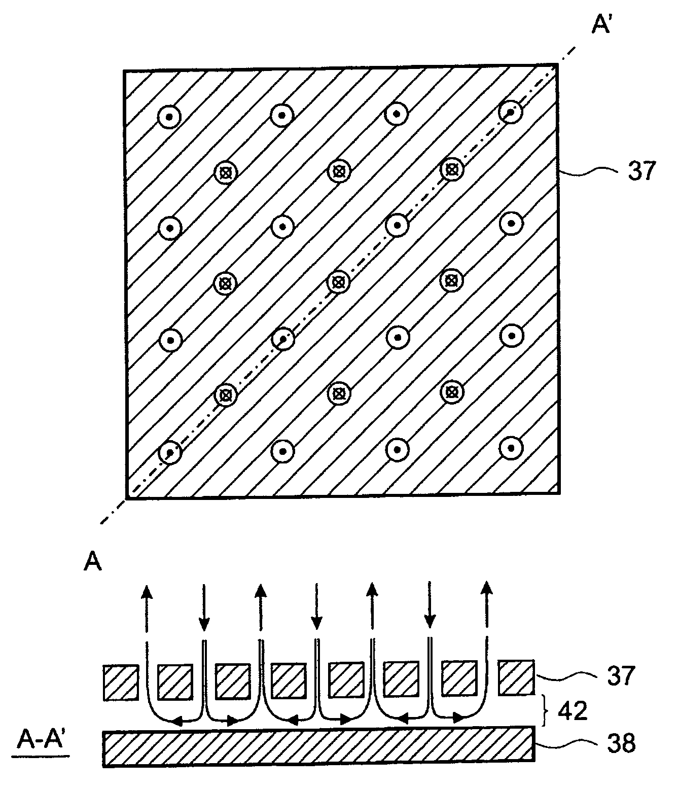
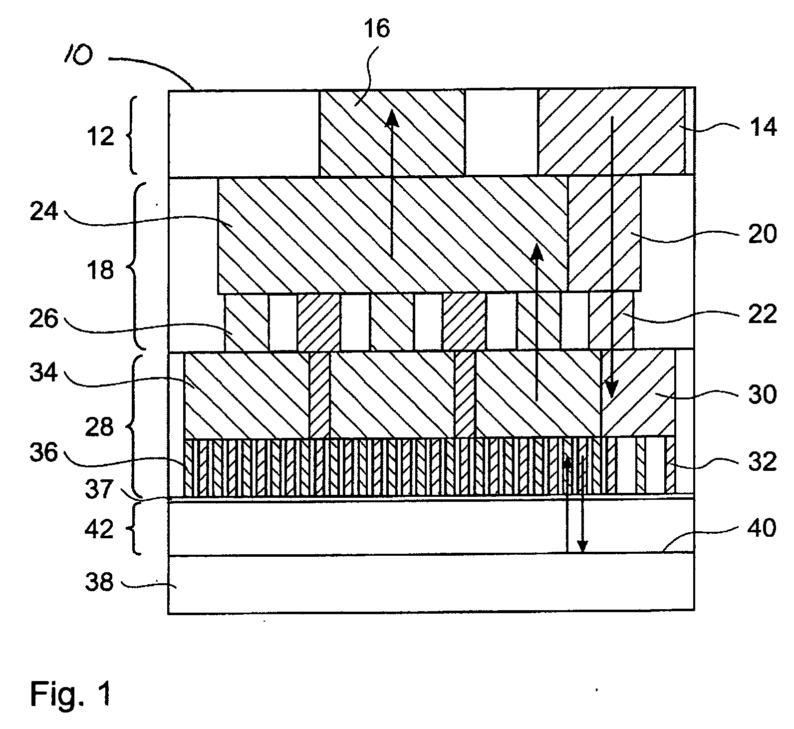
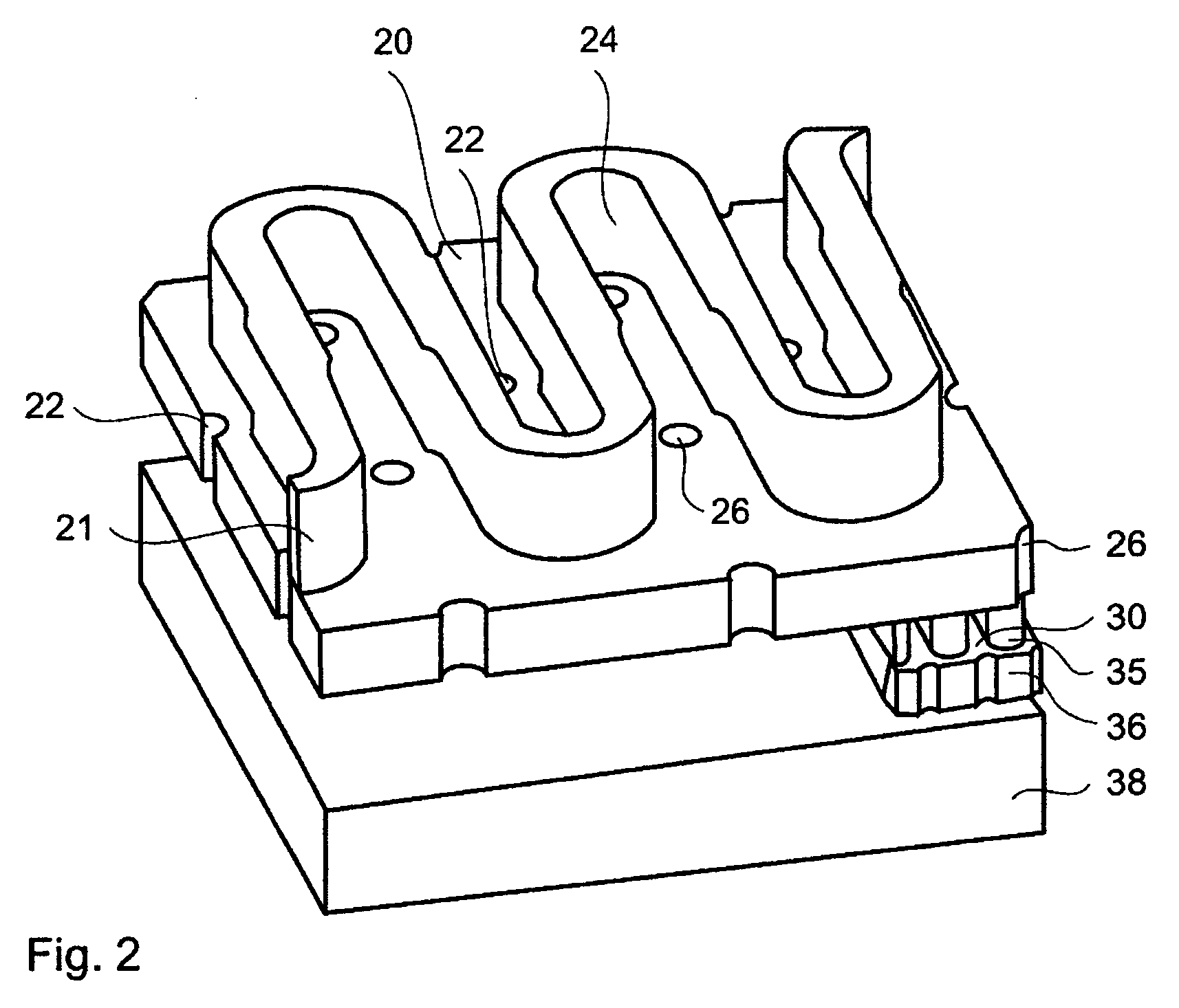
[0062]FIG. 1 shows a cross-sectional view of a portion of an impingement cooler 10 of the present invention. A third level 12 of the impingement cooler 10, also known as an interface layer, comprises a third level inlet 14 and a third level outlet 16. Adjacent to the third level 12 is a second level 18, also known as a manifold layer, comprising a second level manifold input channel 20 connected to several second level inlets 22, and a second level manifold output channel 24 connected to several second level outlets 26. Adjacent to the second level 18 is a first level 28, also known as a jet layer or terminal level, comprising a first level input channel 30 connected to several jet nozzles or first level inlets 32, and a first level output channel 34 connected to several output nozzles or first level outlets 36. The first level inlets 32 and the first level outlets 36 terminate at a jet plate 37. Preferably, the first level inlets 32 and the first level outlets 36 are parallel. A ba...


PUM


Abstract

A cooling device has a large number of closely spaced impinging jets, adjacent an impingement gap, with parallel return paths for supplying coolant flow for the impinging jets with the least possible pressure drop using an interdigitated, branched hierarchical manifold. Surface enhancement features spanning the impingement gap form U-shaped microchannels between single impinging jets and single outlets.

Description

FIELD OF THE INVENTION [0001] This invention relates to a cooling device and particularly relates to impingement coolers in contact with microprocessor chips. TECHNICAL BACKGROUND [0002] In the field of microprocessor chip packages, an effective transfer of thermal energy from a microprocessor chip to a heat sink is important for thermal management of the microprocessor chip. [0003] A known type of active cooling device is an impingement cooler in which coolant flows through channels in the impingement cooler and is then fed through a jet and impinges on the back side of the microprocessor chip. An external pump is used to circulate the coolant between the back side of the microprocessor chip, where heat is absorbed, and a radiator. Heat is subsequently dissipated from the radiator to ambient using, for example, a fan and an air heat exchanger. [0004] A further type of known cooling device for cooling microprocessor chips is a microchannel cooler, as described in “A Practical Implem...

Claims


Application Information

Patent Timeline
IPC IPC(8): H05K7/20
CPCH01L23/4735H01L2924/0002H01L2924/00
Inventor BRUNSCHWILER, THOMAS J.KLOTER, URSLINDERMAN, RYAN JOESPHMICHEL, BRUNOROTHUIZEN, HUGO E.
Owner IBM CORP
Why Eureka
Try Eureka