Adsorption of contaminants from gaseous stream and in situ regeneration of sorbent

a technology of in situ regeneration and sorbent, which is applied in the direction of filtration separation, combustible gas purification/modification, and separation processes, etc., can solve the problems of reducing the adsorption capacity of bonded carbon, labor-intensive, and potentially hazardous and costly procedures, and the replacement period of spent carbon

Inactive Publication Date: 2008-01-08
MCGILL UNIV
View PDF15 Cites 10 Cited by
  • Summary
  • Abstract
  • Description
  • Claims
  • Application Information

AI Technical Summary

Benefits of technology

[0014]It is a further object of the invention to provide a method to remove gaseous contaminants present in gaseous or air streams using activated carbon cloth material as sorbent that can be regenerated “in-situ” effectively, uniformly and very rapidly by passing an electric current through the carbon cloth material under vacuum.
[0016]This invention also provides for the continuous removal of contaminants from a gaseous stream, especially an air stream, on a sorbent, and subsequent rapid non-destructive regeneration of the sorbent. The invention provides for a sorbent bed having minimal pressure drop and a lengthy life expectancy, the original adsorptive capacity of which is essentially restored by regeneration, and where bed depth is limited only by the capacity of the host system.
[0023]b) placing said chamber under vacuum, and passing an electric current through said carbon cloth material and generating heat in said carbon cloth material effective to desorb said contaminant from said carbon cloth material.
[0043]The desorption of contaminant under vacuum from the carbon cloth material regenerates the activated carbon cloth, essentially to its original adsorptive capacity. The operation in a vacuum avoids degradation of carbon cloth by air and permits use of lower heating temperatures for desorption which similarly avoids degradation of the carbon cloth exhibited at high temperatures.

Problems solved by technology

Inherent problems associated with such systems include high pressure drops and the periodic replacement of the spent carbon, a labor intensive, potentially hazardous and costly procedure.
Although this addresses the problem of high pressure drop across the filtration medium, it leads to a decrease in adsorptive capacity of the bonded carbon and the need for periodic replacement remains.
However, as for the other forms, it must periodically be replaced, and the time between replacements can be comparatively short.
Replacement with virgin activated carbon is costly and laborious.
Movement of the spent carbon off site for regeneration incurs transportation and labor costs and degradation of the medium.
The regeneration gases burn the carbon medium with a concomitant loss in both the amount of active carbon and the adsorptive capacity.
Regeneration of spent carbon by means of vacuum procedures have been largely ineffective to date, because adsorbate volatilization requires thermal energy and vacuum desorption has a chilling effect on the carbon which cannot be offset because the vacuum environment is known to be a very efficient thermal isolator.
Hence, for all available processes to date, heat energy cannot be added to the chilled carbon during vacuum adsorption.
At best, the process requires an inordinate amount of time to achieve acceptable regeneration.
In general, for all the aforementioned regeneration procedures, the regenerated activated carbon never attains its original adsorptive capacity because there is a residual adsorbate which resists removal.
The result is that eventually the regenerated carbon does not satisfy contaminant removal requirements, and must be replaced.
However, only limited successes have been achieved with this procedure when applied to granulated / pelletized / powdered carbon, because of non-uniform heating patterns, hot spots and short circuits.
The use of air is not recommended since it invariably leads to significant loss of carbon over time by oxidation; and the method requires the use of large volumes of inert gaseous during the regeneration phase which may take three hours or more depending on loading and adsorbate characteristics.

Method used


Image

  • Adsorption of contaminants from gaseous stream and in situ regeneration of sorbent
  • Adsorption of contaminants from gaseous stream and in situ regeneration of sorbent
  • Adsorption of contaminants from gaseous stream and in situ regeneration of sorbent

Examples


Embodiment Construction

[0034]a) Adsorption and Desorption

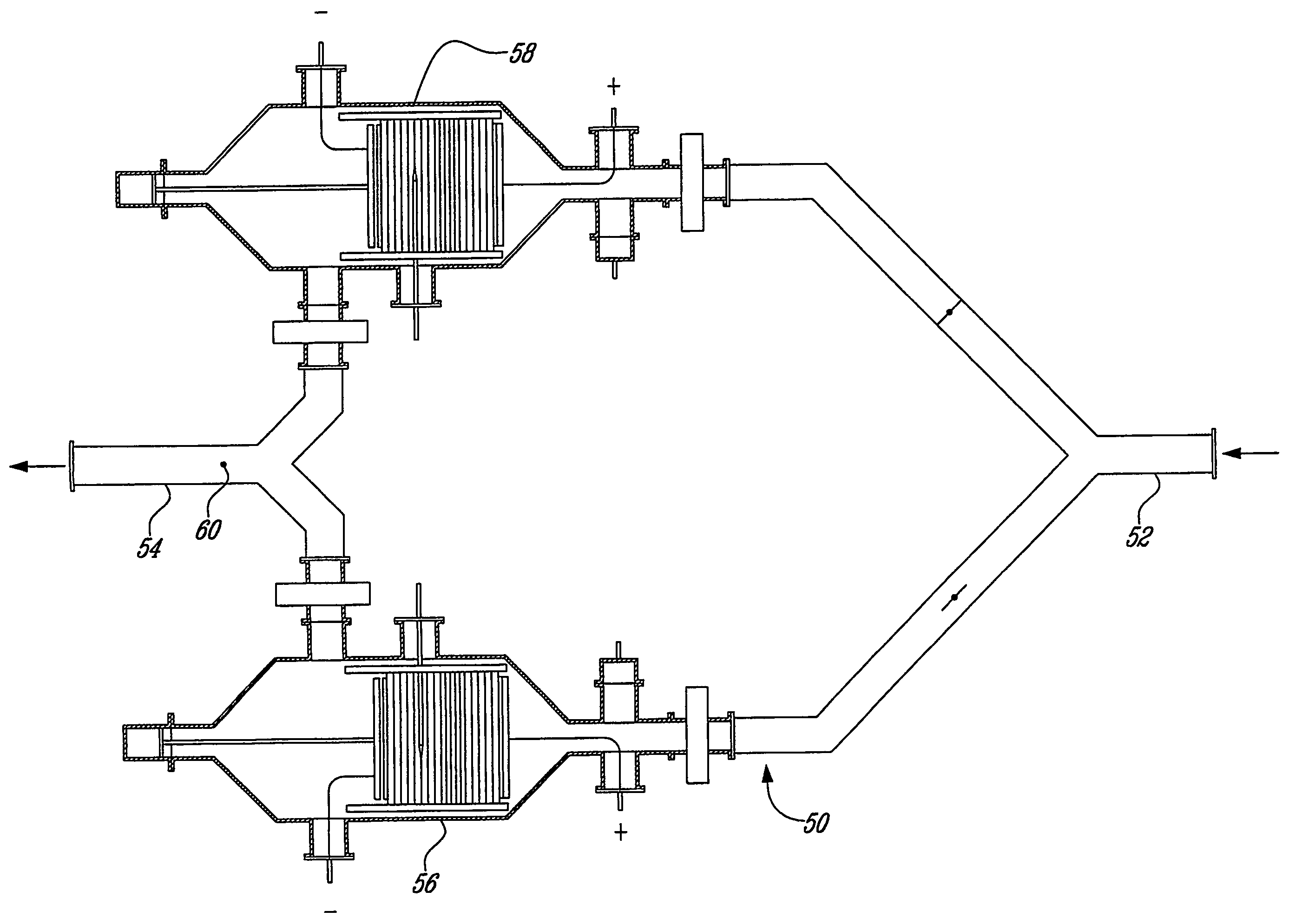
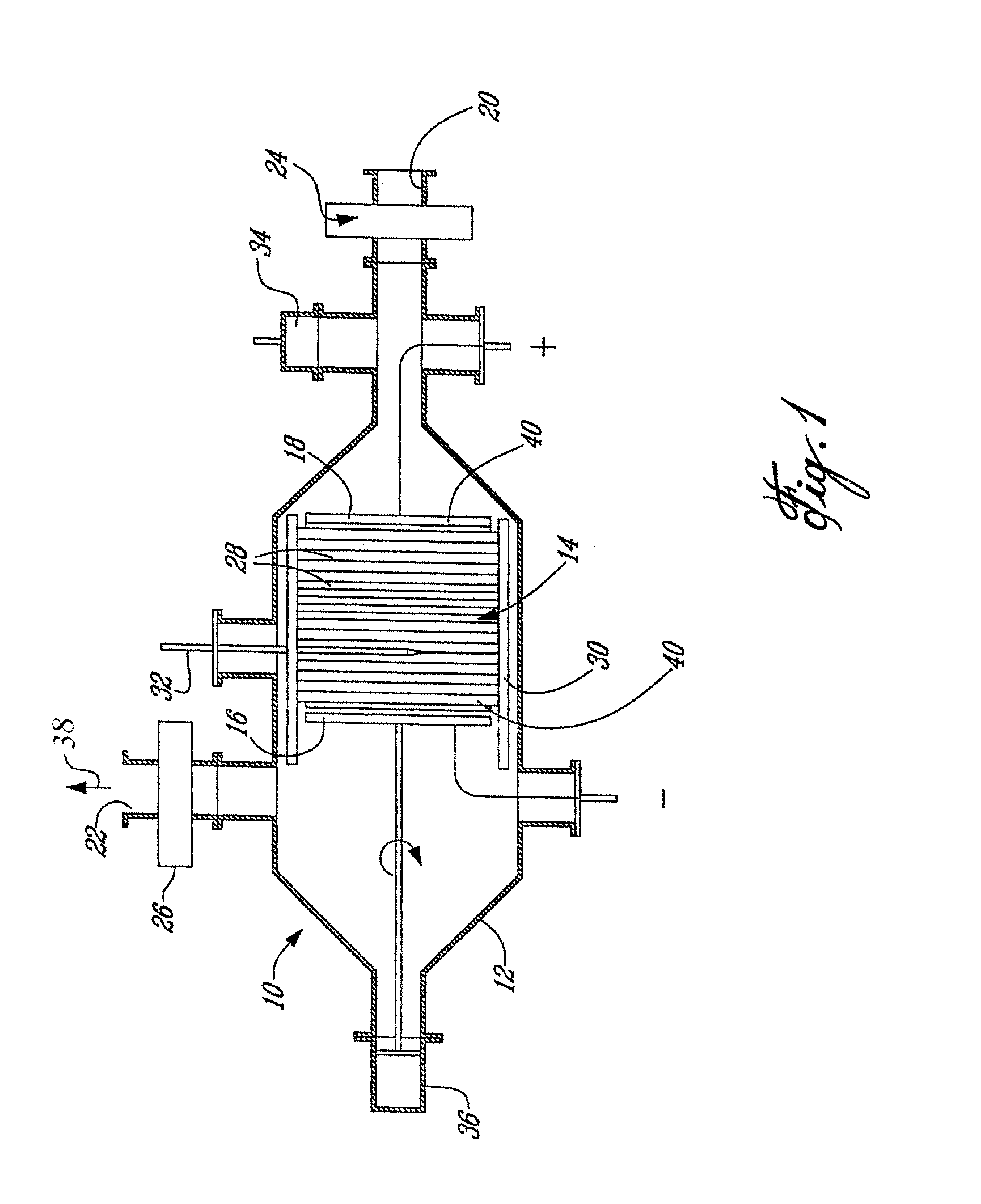
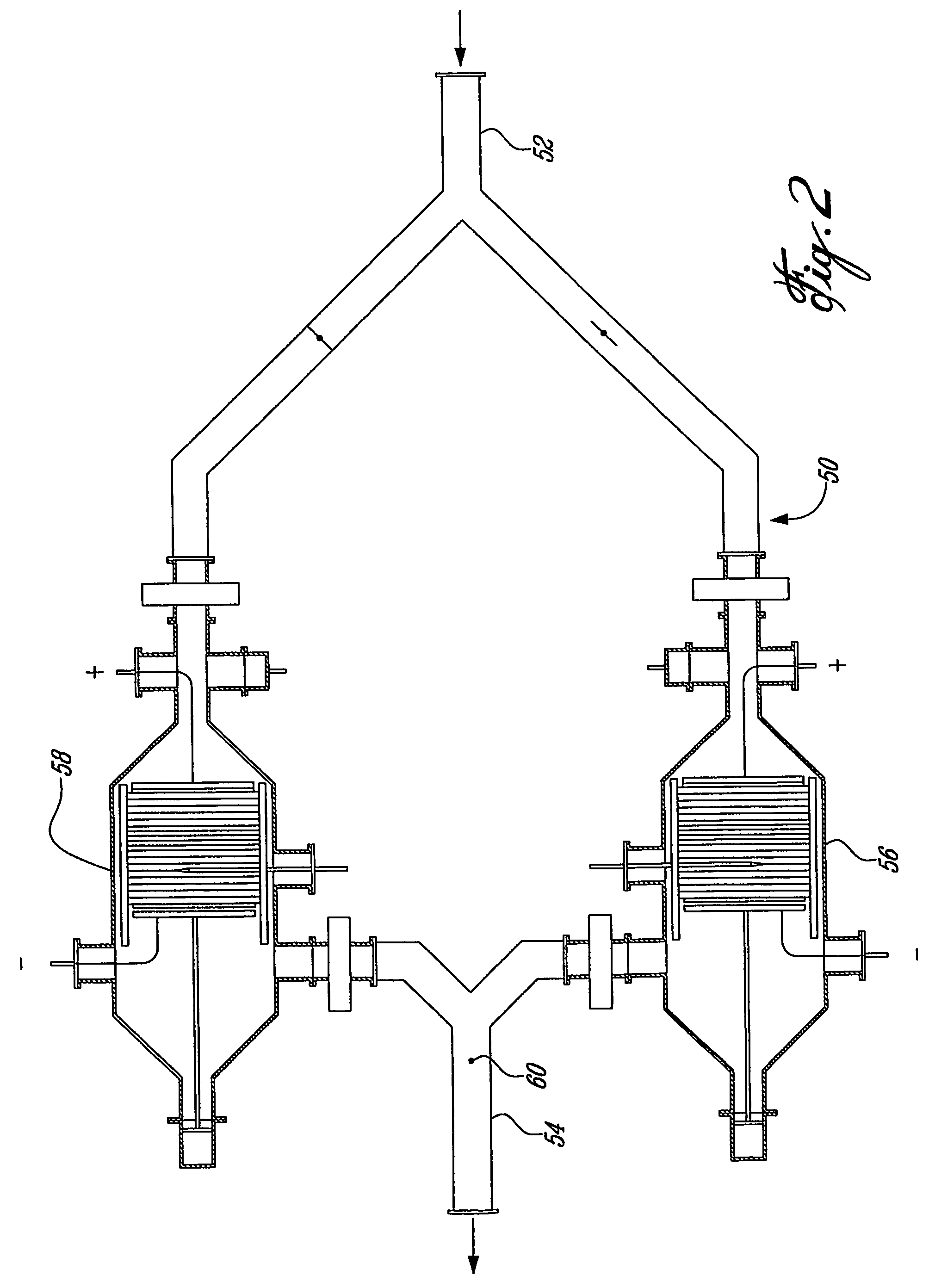
[0035]The invention contemplates adsorption of contaminant from a gaseous stream bearing the contaminant on an activated carbon cloth material which is electrically conductive and resiliently compressible.

[0036]The invention also contemplates desorption of the contaminant from the cloth material loaded with adsorbed contaminant.

[0037]The adsorption is typically carried out at ambient temperatures of 10 to 30° C., more especially about 20° C. by flowing a gaseous stream bearing the contaminant through the activated cloth material; the contact time for adsorption is typically less than 1 second and more especially less than 0.1 second.

[0038]The contaminant may be a useful material which may be recovered for re-use in a subsequent step, for example, solvent which accumulates in the atmosphere in industrial premises; or it may be a noxious or non-useful material which is to be collected for disposal. In general, the contaminants will be organic substanc...


PUM

PropertyMeasurementUnit
temperatureaaaaaaaaaa
temperaturesaaaaaaaaaa

Abstract

Contaminant is removed from a gaseous stream, especially an air stream bearing the contaminant, by adsorption on a sorbent which is a resiliently compressible, electrically conductive, activated carbon cloth material, leaving a gaseous stream liberated of the contaminant; the carbon cloth material loaded with the contaminant may be regenerated by desorption of the contaminant; the carbon cloth material loaded with contaminant is housed in a vacuum and electric current is passed through the carbon cloth material generating heat in the cloth material which is effective to desorb the contaminant which is exhausted under vacuum; the level of heat generated is varied as required, typically to develop a temperature of 250 to 500° C. in the cloth material, by varying the compression of the cloth material; desorption is typically achieved in about 30 minutes at a vacuum of 10 Torr or less.

Description

[0001]This application claims the priority benefit of PCT / CA02 / 01915, filed Dec. 11, 2002, which claims the priority benefit of U.S. provisional application Ser. No. 60 / 340,874, filed Dec. 19, 2001, which is incorporated herein by reference.TECHNICAL FIELD[0002]This invention relates to a method and apparatus or device for removing a contaminant from a gaseous stream bearing the contaminant; the invention also relates to a method and apparatus or device for desorbing a contaminant from a carbon cloth material loaded with adsorbed contaminant.[0003]More especially, the invention relates to the removal of gaseous contaminants from an air stream by an activated carbon cloth sorbent and the subsequent “in-situ” regeneration of the carbon cloth by the direct application of an electric current while the electro thermally heated carbon cloth is maintained under vacuum and the concomitant collection of the contaminants or their thermal degradation products from the evacuated air for recover...

Claims


Application Information

Patent Timeline
Patent Type & Authority Patents(United States)
IPC IPC(8): B01D53/04B01J20/34B01D53/02B01J20/28
CPCB01D53/02B01D53/04B01D53/0438B01J20/20B01J20/28033B01J20/28052B01J20/3416B01J20/3441B01D53/0415B01D2253/102B01D2257/90B01D2258/02B01D2259/40009B01D2259/40096B01D2259/40098B01D2259/402B01D2259/4146B01D2259/4508B01D2259/4575B01J20/34
Inventor FARANT, JEAN-PIERREDESBIENS, GERALD
Owner MCGILL UNIV
Why Eureka
Try Eureka