Fuel and air flow control in a multi-stack fuel cell power plant

a fuel cell and multi-stack technology, applied in the direction of electrochemical generators, cell components, cell component details, etc., can solve the problems of complex reactant transfer line assemblies and become complicated, and achieve the effect of simple fuel and air distribution mechanism and minimal pressure drop

Active Publication Date: 2006-09-19
AUDI AG
View PDF4 Cites 12 Cited by
  • Summary
  • Abstract
  • Description
  • Claims
  • Application Information

AI Technical Summary

Benefits of technology

[0005]This invention relates to a multi-fuel cell stack power plant which employs a simplified fuel and air distribution mechanism. The power plant of this invention includes a plurality of separate fuel cell stacks which utilize common fuel and air streams to produce electricity. The fuel cell stacks are connected in parallel and in tandem so that a plurality of stacks form a first stage in the power plant, and one or more additional stacks form a second stage in the power plant. All of the stacks in each stage of the power plant are operatively connected to an intermediate fuel and air distribution manifold which directs fuel exhausted from the stacks in the first stage to the stack(s) in the second stage. The stacks in the first stage are fueled in parallel, and the stack(s) in the second stage are fueled in tandem with the first stage. The transfer of fuel from the first stage to the second stage is accomplished with minimum and uniform gas pressure drop so as to ensure that there will be no maldistribution of flow in the manifold from the first stage stacks to the second stage stacks. The use of the distribution manifold enables one to form a more compact power plant and to uniformly distribute and collect reactants to each fuel cell stack in the power plant. The uniform collection / distribution of the flows, with minimal pressure drop, ensures that the fuel cell stacks will perform as predicted.
[0009]It is a further object of this invention to provide a fuel cell power plant of the character described wherein the stacks in both stages are mounted on a common reactant transfer manifold so as to minimize the volume of the plant and simplify plant assembly by minimizing the number of reactant flow connections in the plant and thereby minimize plant assembly errors.

Problems solved by technology

This approach involves the use of a plurality of reactant transfer lines from one stage to the next, which can become complicated and require complicated reactant transfer line assemblies.

Method used


Image

  • Fuel and air flow control in a multi-stack fuel cell power plant
  • Fuel and air flow control in a multi-stack fuel cell power plant
  • Fuel and air flow control in a multi-stack fuel cell power plant

Examples


Embodiment Construction

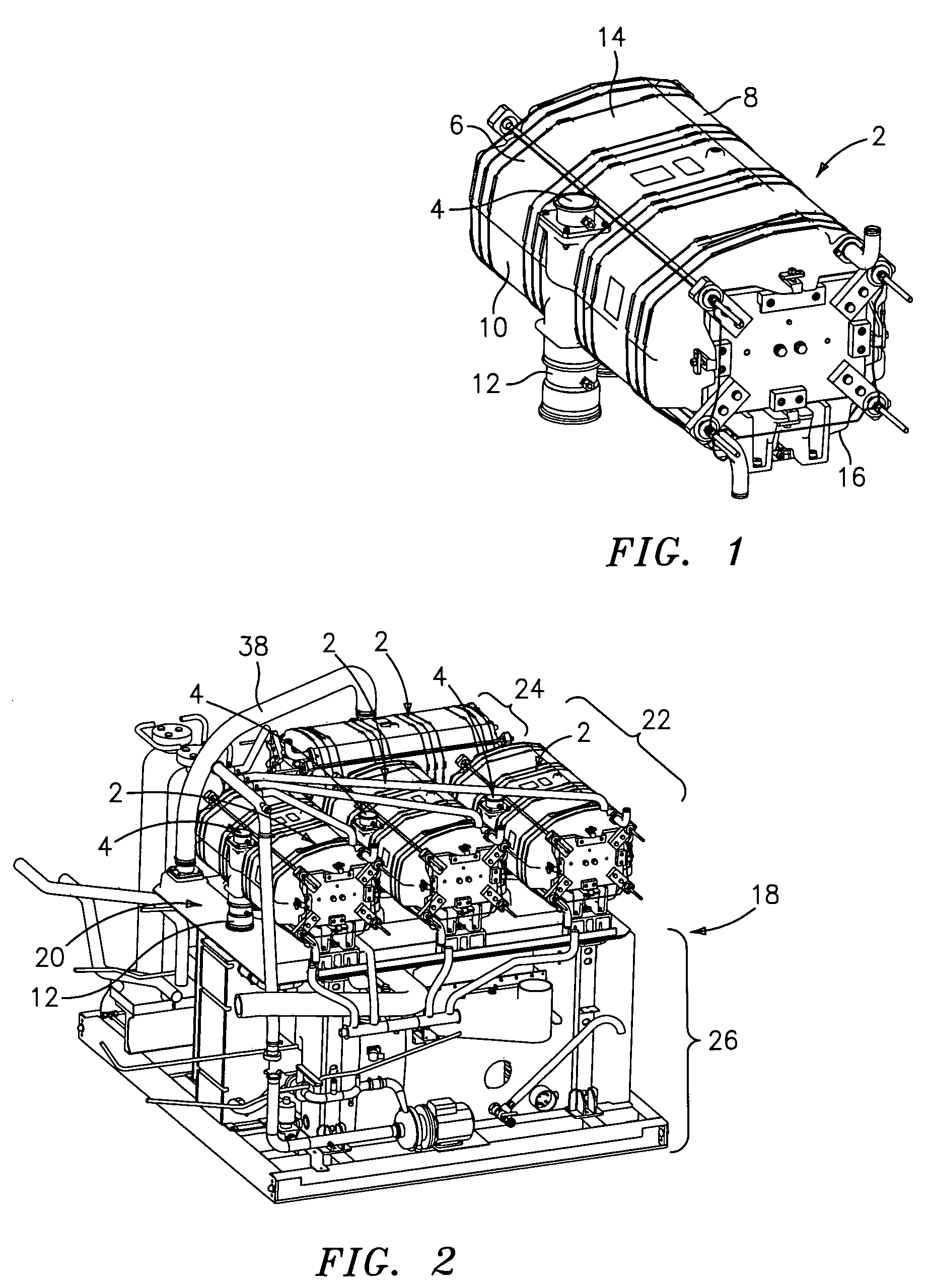
[0018]Referring now to the drawings, FIG. 1 is a perspective view of a fuel cell stack which is configured for use in connection with the multi-stage, multi-stack fuel cell power plant formed in accordance with this invention, which stack is denoted generally by the numeral 2. The stack 2 has a fuel inlet connection 4 which opens into a fuel inlet manifold 6. The fuel inlet manifold 6 feeds fuel through the cells 14 in the stack 2 to a fuel reversal flow manifold 8 on the opposite side of the stack 2, whereupon the fuel flows back to a fuel outlet manifold 10. The fuel stream exits the stack 2 via a fuel outlet connection 12. Air is passed through the cells in the stack via the inlet and outlet manifold 16.

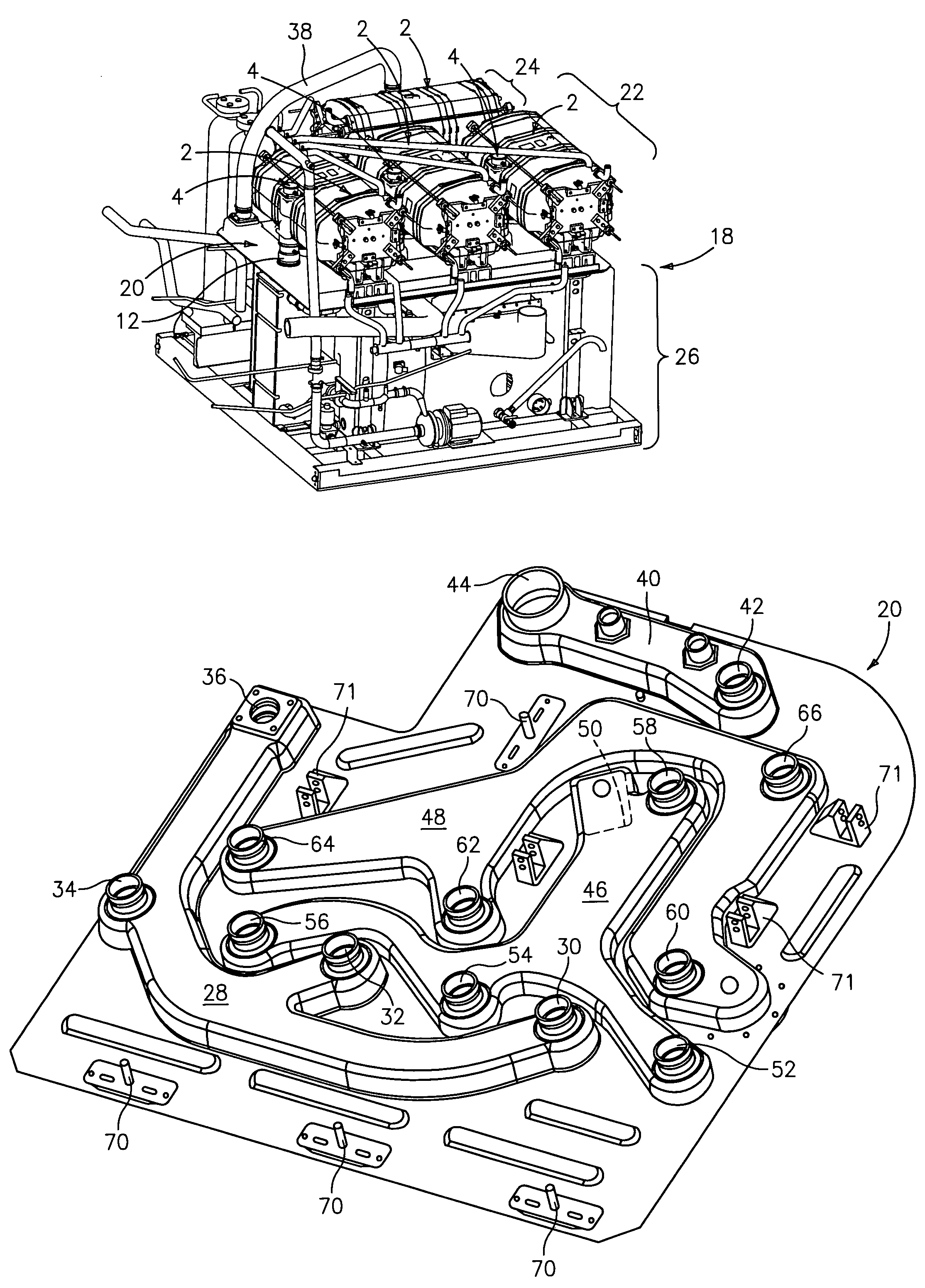
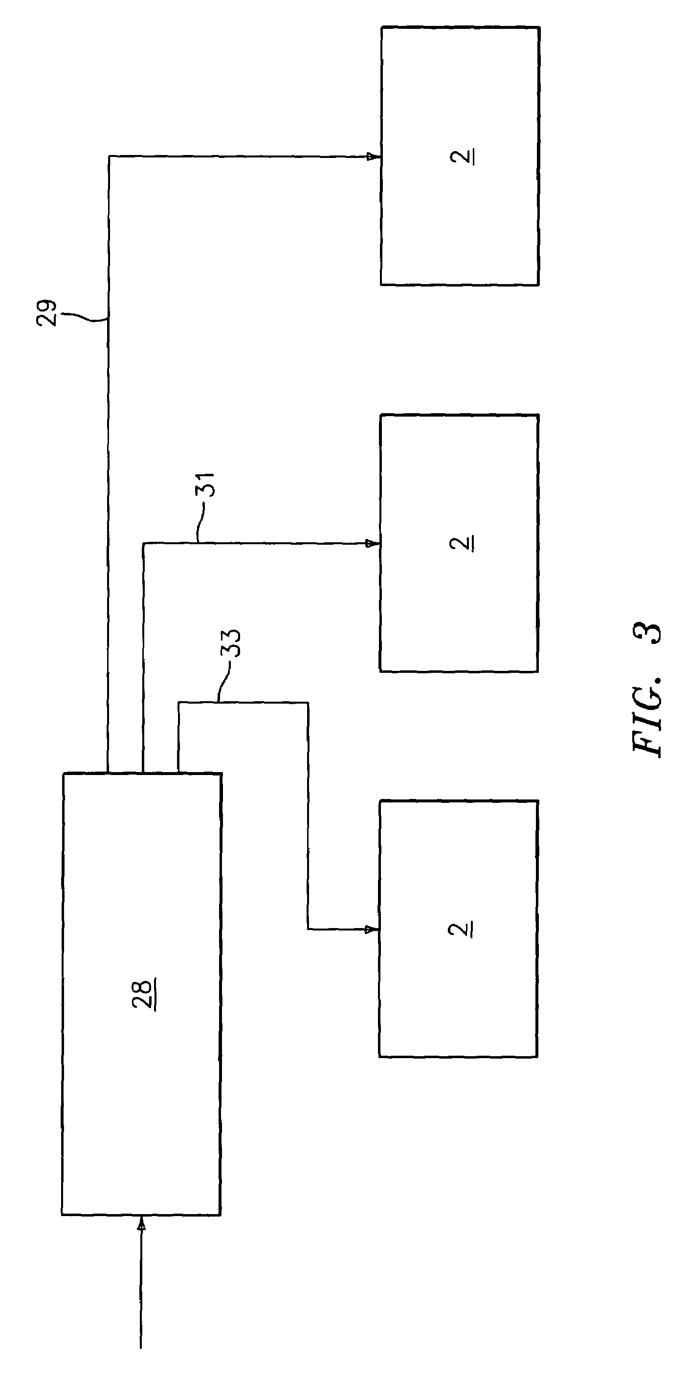
[0019]Referring now to FIG. 2, there is shown a modular fuel cell power section which is designated generally by the numeral 18. The power section 18 includes four fuel cell stacks 2 which are all mounted on a common gas distribution manifold 20. The stacks 2 are grouped into two ...


PUM

PropertyMeasurementUnit
pressure dropaaaaaaaaaa
poweraaaaaaaaaa
pressureaaaaaaaaaa

Abstract

A fuel cell power plant includes a plurality of fuel cell stacks which are operatively associated with each other so that both the air stream and fuel stream for the stacks are shared by each of the stacks in the power plant. The air and fuel streams are fed into an initial stack stage in the power plant, and after the air and fuel streams pass through the initial stack stage, the fuel exhaust streams are then fed into one or more subsequent stack stages in the power plant. The fuel streams are passed from the initial fuel cell stack stage to the subsequent fuel cell stack stage by means of a common manifold on which each of the fuel cell stacks in the power plant is mounted. The air streams are routed to all of the fuel cell stacks via a channel in the common manifold.

Description

TECHNICAL FIELD[0001]The present invention relates to a method and system for controlling the flow of air and fuel to a plurality of fuel cell stacks in a multi-stage fuel cell power plant wherein at least two fuel cell stacks in a first stage in the power plant are connected in tandem with one or more additional fuel cell stack(s) in a second stage in the power plant. More particularly, this invention relates to a method and system of the character described wherein all of the fuel cell stacks in the power plant are mounted on a common air and fuel-distributing manifold which feeds fuel to the fuel cell stacks in the first stage and then feeds first stage fuel exhaust to the fuel cell stack(s) in the second stage, whereby all of the fuel cell stacks in the power plant are operated with a single stream of fuel.BACKGROUND OF THE INVENTION[0002]Electricity is produced by fuel cell power plants which electrochemically convert a hydrocarbon-containing fuel stream, or a hydrogen stream, ...

Claims


Application Information

Patent Timeline
Patent Type & Authority Patents(United States)
IPC IPC(8): H01M8/00H01M2/14H01MH01M8/02H01M8/04H01M8/24
CPCH01M8/04097H01M8/2415H01M8/249H01M8/2485Y02E60/50H01M8/2457
Inventor KURTZ, JENNIFER M.BRINDLEY, THOMAS A.
Owner AUDI AG
Why Eureka
Try Eureka