
Device and method for noninvasive ultrasonic treatment of fluids and materials in conduits and cylindrical containers

Inactive Publication Date: 2009-02-12
BATTELLE MEMORIAL INST
View PDF32 Cites 60 Cited by
  • Summary
  • Abstract
  • Description
  • Claims
  • Application Information

AI Technical Summary

Benefits of technology

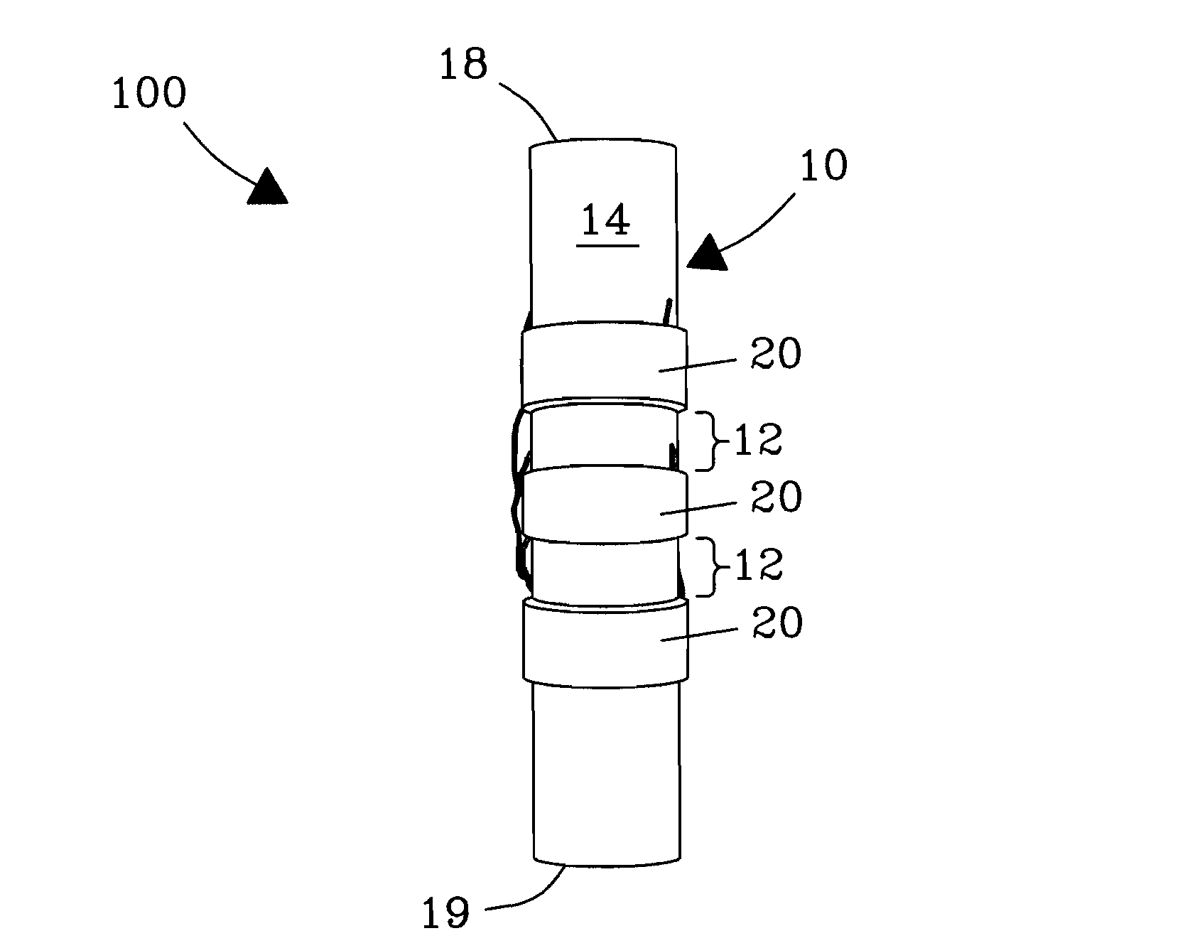
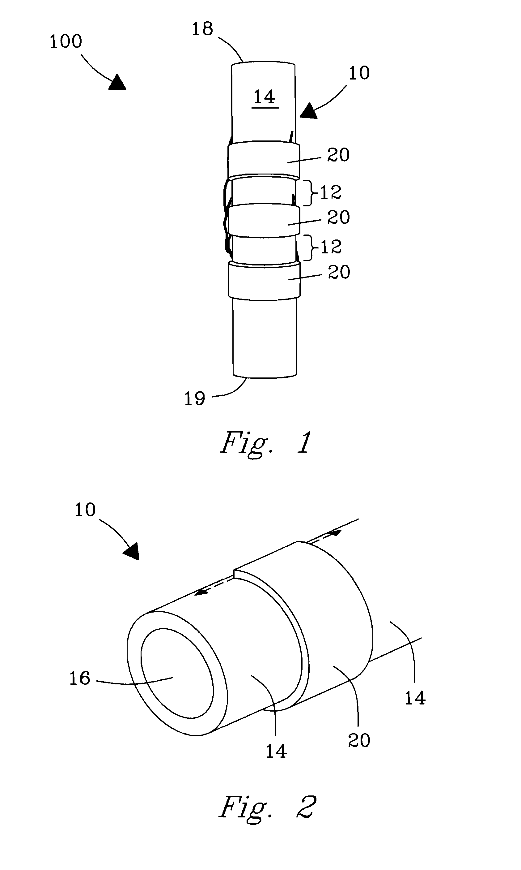
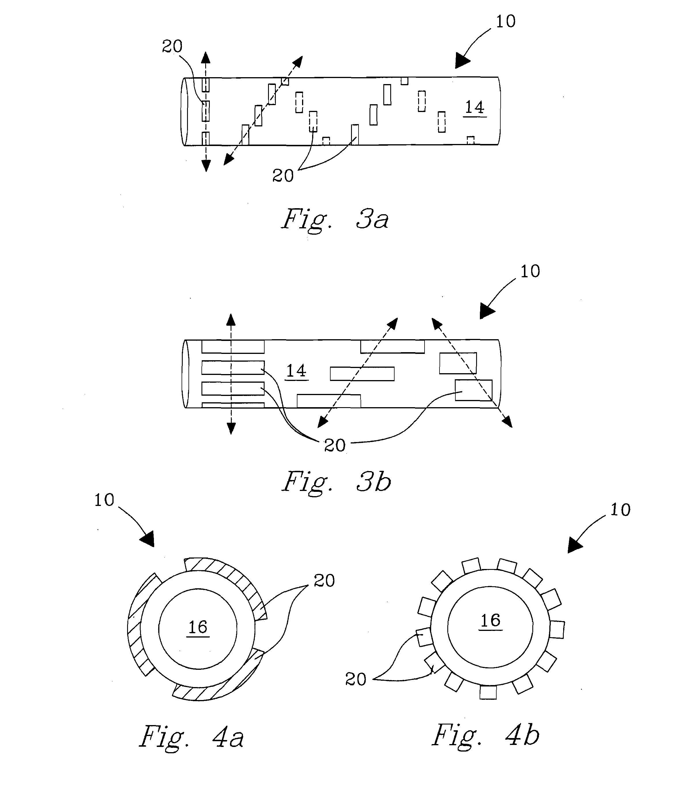
[0007]The present invention is a device and method for processing of fluids, including, e.g., crude oil and other viscous and light fluids, through use of an ultrasonic energy transmitting device that attaches to, and substantially surrounds, a conduit, a tube, or a container in which fluids, or other materials are placed. By substantially surrounding the conduit, tube, or container onto which the transmitting device is placed and transmitting focused and unfocused ultrasonic energy into the contained fluid or material in a way that does not require an intrusive foreign body to be placed into the fluid or material, various problems associated with prior art devices are overcome. Furthermore, as the detailed descriptions further clarify, such configurations provide exceptional advantages over the prior art in terms of greater efficacy and efficiency in transmitting energy to the material or fluid of interest and provides for a variety of treatment options and advantages over the prior art.
[0008]In descriptions of the preferred embodiment of the invention set forth hereafter, intense, cylindrically focused ultrasonic energy produced by the invention has been shown to: cleave chemical bonds and form reactive radicals; induce rapid heating in fluids, including, e.g., crude oils and other viscous Fluids; and separate emulsions using both cavitating and non-cavitating ultrasonic energy. In other embodiments, the invention has been utilized with other additives to enhance effectiveness of the various methodologies described herein. To encourage formation of favorable products from ultrasonic cavitation, use of water or other co-solvents and / or catalysts may be necessary, depending on chemical nature of the treated system. It is reasonable to believe that ultrasonic vibrational energy provided by the invention may also mitigate accumulation of pipe-fouling deposits on the inner diameters of pipe walls. The robustness, adaptability, noninvasiveness, and large sonication volume provided by the invention allows ultrasonic processing of fluids and materials to move beyond laboratory scale processing to industrial scale processing for a variety of fluid and / or material processing applications.

Problems solved by technology

However, ultrasonic probes are prone to a variety of problems related to their use, including, but not limited to, e.g., degradation and / or erosion of the tips of the probes as a function of age (e.g., hours of use), subsequent contamination of materials into which these probes with tip probe particulates are placed, increasingly inefficient transmission of ultrasonic energy with increasing probe tip erosion, disruption of flow of materials around the probes, small focal volumes or areas of effectiveness, and other related problems.
In batch ultrasound devices, e.g., cleaning devices, sonic energy is typically unfocused and is further limited for flow processing and applications.
Such systems are generally limited to frequencies in the 30-50 kHz range; and the magnetic systems are usually less than 50% efficient due to the energy lost in heating of coils and effects of magnetic hysteresis.
Additionally, generators used in conjunction with these systems, even if well tuned, are generally no more than 70% efficient, meaning that overall power delivery is between 35% and 40% efficient.
With increasing energy costs, the impact on operational costs of a large magnetostrictive system cannot be underestimated.

Method used


Image

  • Device and method for noninvasive ultrasonic treatment of fluids and materials in conduits and cylindrical containers
  • Device and method for noninvasive ultrasonic treatment of fluids and materials in conduits and cylindrical containers
  • Device and method for noninvasive ultrasonic treatment of fluids and materials in conduits and cylindrical containers

Examples


example 1

(Exemplary Operating and Processing Conditions)

[0041]In an exemplary, non-limiting processing operation, the PZT rings were powered by a commercially available 50-ohm arbitrary output waveform function generator (Hewlett Packard, Palo Alto, Calif., USA) and a commercially available 50-ohm output radio frequency (RF) power amplifier (Electronics & Innovation, Rochester, N.Y., USA). The function generator was tuned to provide a continuous or pulsed sinusoidal wave of a predetermined frequency and voltage. Output signal from the function generator was provided to the input of the RF power amplifier where it was amplified before being supplied to the PZT rings. The PZT rings were wired in parallel to deliver a uniform voltage.

[0042]A perpetual mismatch was observed between the 50-ohm electronics and the inherent electrical impedances of the PZT rings at their resonance frequencies (i.e., the load). This impedance mismatch affected overall efficiency of the system, requiring the amplifie...

example 2

(Static Mode Processing of Mexican Crude Oil)

[0045]A low grade, heavy (i.e., 12.67 API) Mexican crude oil was processed in static mode 1) at resonance frequencies of 625 kHz (thickness mode) and 90 kHz (length mode) and 2) off-resonance frequencies of 80 kHz, 700 kHz, and 825 kHz. In the preferred embodiment of the invention configured for static processing of crude oils, container 10 had a wall thickness of 3.264 mm and a length of 20.71 mm. PZT rings 20 had dimensions of: 62.23 mm O.D.; 55.63 mm I.D. Outerwall 14 was constructed of a 64 mm O.D. Schedule-40 carbon steel pipe segment, chosen due to its use in crude oil production piping. Three (3) PZT rings were mounted on the outside of the pipe segment. Temperature data during static sonication of the crude oil are presented in Tables 1 and 2. Viscosity data are presented in Table 2. FIG. 7 plots changes in temperature of the crude oil in the center axial zone of the reactor as a function of sonication time.

TABLE 1Temperature Prof...

example 3

(Dynamic Flow Processing of Alaskan Crude Oil)

[0051]A heavy Alaskan crude oil (19 API), characterized as a 38 wt % brine-in-crude oil emulsion, was sonicated in the flow loop of the test configuration that contains the adapted crude oil processing technology (herein frequently referred to as the “test leg”) under dynamic flow processing conditions. The flow loop 10 was constructed of a 49.8 mm O.D. Schedule-40 carbon steel pipe. The flow loop comprised eighteen (18) PZT rings 20, but is not limited thereto. In the instant configuration, the PZT rings used for the flow loop were of a slightly different dimension than those used for static processing described in Example 2, including a 61.0 mm O.D.; 48.8 mm I.D.; 6.096 mm wall; and 30.48 mm length. Rings of the test leg were spaced 25.4 mm to 27.9 mm apart (i.e., at least 1.5 wavelengths at 65 kHz) to ensure constructive overlap of the sonicated volumes produced by neighboring rings. A 114 L (30 gallon) sample of the low grade, heavy ...


PUM


Abstract

A system, method, and device are described for ultrasonic treatment of viscous fluids, including, e.g., crude oils that provide a variety of desired modifications. The invention includes a container having a circumvolving outer wall configured to allow passage of a quantity of a material within a passageway therein and ultrasonic transducers that attach to and circumvolve the outer wall of the container. The ultrasonic transducers transmit ultrasonic energy into material within the container at preselected frequencies thereby achieving desired effects.

Description

FIELD OF THE INVENTION[0001]The invention relates generally to ultrasonic devices and methods for treatment of fluids, including, e.g., crude oils and other fluids in a pipe (e.g., a crude oil production pipe), a tube (e.g., microfluidic tubes), or cylindrical container (e.g., a chemical batch reactor). In preferred embodiments, the invention relates to devices and methods for introducing and utilizing non-cavitating and / or cavitating ultrasonic energy to provide a variety of desired physical and chemical property modifications to fluids and materials, including, e.g., cleavage of chemical bonds and formation of reactive radicals; changing viscosity, inducing rapid heating, and separating phases in multiphase systems.BACKGROUND OF THE INVENTION[0002]Ultrasound is a pressure wave and a form of vibrational mechanical energy. When ultrasound propagates through, and interacts with, a fluid, the energy is attenuated by scattering or absorption. At lower sub-cavitational powers, ultrasoni...

Claims


Application Information

Patent Timeline
IPC IPC(8): B01J19/12C07C1/00
CPCB01F5/10B01F11/0241C10G33/06B01J19/10B01F11/0266B01F25/50B01F31/84B01F31/86
Inventor DENSLOW, KAYTE M.POSAKONY, GERALD J.BOND, LEONARD J.DIAZ, AARON A.ALNAJJAR, MIKHAIL S.FRANZ, JAMES A.
Owner BATTELLE MEMORIAL INST
Learn More