Nutating pump with reduced pulsations in output flow

a nutating pump and output flow technology, applied in the direction of pump components, positive displacement liquid engines, pump components, etc., can solve the problems of difficult use of a constant motor speed, difficulty in accurately dispense fluid using a partial revolution, and small amount of nutating pumps for paint colorants, so as to reduce the peak flow rate, reduce or eliminate the occurrence of splashing, pressure spikes and motor stalling

Active Publication Date: 2010-01-19
FLUID MANAGEMENT LLC
View PDF8 Cites 3 Cited by
  • Summary
  • Abstract
  • Description
  • Claims
  • Application Information

AI Technical Summary

Benefits of technology

[0030]In another refinement, multiple pistons, or multiple nutating pump assemblies may be combined with proper timing, to achieve similar improvement in flow patterns.
[0034]As a result, the disclosed nutating pumps reduce the peak flow rate, produce output in both portions of the dispense cycle, and make the flow pulsations less severe, thereby reducing or eliminating the occurrence of splashing, pressure spikes and motor stalling.
[0035]Although any diameter could be used, a reduced diameter for the proximal section of the piston that is 0.7071 times the diameter of the main section or pump section of the piston diameter, the displacement of the second chamber will be one-half that of the first chamber, resulting in a smooth flow.
[0036]In a refinement, the flow from the first chamber is routed entirely through the second chamber, to eliminate unflushed “dead” volumes, and to prevent or remove air pockets.
[0040]Further advantages of the disclosed pumps include the concept that the peak flow per motor step (or motor angular rotation) is one-half that of the original pump design, allowing for increased resolution and accuracy of small dispense amounts from the pump. This is particularly true of the partial-revolution dispenses done while taking into account the flow during each portion of the rotation.

Problems solved by technology

Such piston operation results in a specific amount of fluid pumped by the nutating pump with each revolution of the piston.
As a result, existing nutating pumps for paint colorants can be very small.
However, using a partial revolution to accurately dispense fluid is difficult due to the non-linear output of the nutating pump dispense profile vs. angle of rotation as shown in FIG. 1A.
While operating the pump at a constant motor speed has its benefits in terms of simplicity of controller design and pump operation, the use of a constant motor speed also has inherent disadvantages, some of which are addressed in U.S. Pat. No. 6,749,402 (Hogan et al.).
Specifically, in certain applications, the maximum output flow rate illustrated on the left side of FIG. 1A can be disadvantageous because the output fluid may splash or splatter as it is being pumped into the output receptacle at the higher flow rates.
For example, in paint or cosmetics dispensing applications, any splashing of the colorant as it is being pumped into the output container results in an inaccurate amount of colorant being deposited in the container but also colorant being splashed on the colorant machine which requires labor intensive clean-up and maintenance.
Obviously, this splashing problem will adversely affect any nutating pump application where precise amounts of output fluid are being delivered to an output receptacle that is either full or partially full of liquid or small output receiving receptacles.
To avoid splashing altogether, the motor speed would have to be reduced substantially more than 20% thereby making the choice of a nutating pump less attractive despite its high accuracy.
A further disadvantage to the pulsed flow shown in FIG. 1A is an accompanying pressure spike that cause an increase in motor torque.
In addition to the splashing problem of FIG. 1A, the large pressure drop that occurs within the pump as the piston rotates from the point where the dispense rate is at a maximum to the point where the intake rate is at a maximum (i.e. the peak of the curve shown at the left of FIG. 1A to the valley of the curve shown towards the right of FIG. 1A) can result in motor stalling for those systems where the motor is operated at a constant speed.
As a result, motor stalling will result in an inconsistent or non-constant motor speed, there by affecting the sinusoidal dispense rate profile illustrated in FIG. 1A, and consequently, would affect any control system or control method based upon a preprogrammed sinusoidal dispense profile.
The stalling problem will occur on the intake side of FIG. 1A as well as the pump goes from the maximum intake flow rate to the maximum dispense flow rate.
However, the nutating pump design of Hogan et al. as shown in FIG. 2, while reducing splashing, still results in a start / stop dispense profile and therefore the dispense is not a pulsation-free or completely smooth flow.
Further, the abrupt starting and stopping of dispensing followed by a significant lag time during the fill portion of the cycle still presents the problems of significant pressure spikes and bulges and gaps in the fluid stream exiting the dispense nozzle.
Thus, the only modifications that can be made to the cycle shown in FIG. 2 to reduce the abruptness of the start and finish of the dispensing portion of the cycle would result in increasing the cycle time and any reduction in the maximum fill rate to reduce pressure spiking and motor stalling problems would also result in an increase in the cycle time.

Method used


Image

  • Nutating pump with reduced pulsations in output flow
  • Nutating pump with reduced pulsations in output flow
  • Nutating pump with reduced pulsations in output flow

Examples


Embodiment Construction

[0067]Turning first to FIG. 1D, a prior art piston 10 is shown with a narrower portion 11 that is linked or coupled to the motor. The wider section 12 is the only section disposed within the pump chamber. The wider section 11 includes a flattened portion 13 which is the active pumping area. The differences between the prior art piston 10 of FIG. ID and the pistons of this disclosure will be explained in greater detail below.

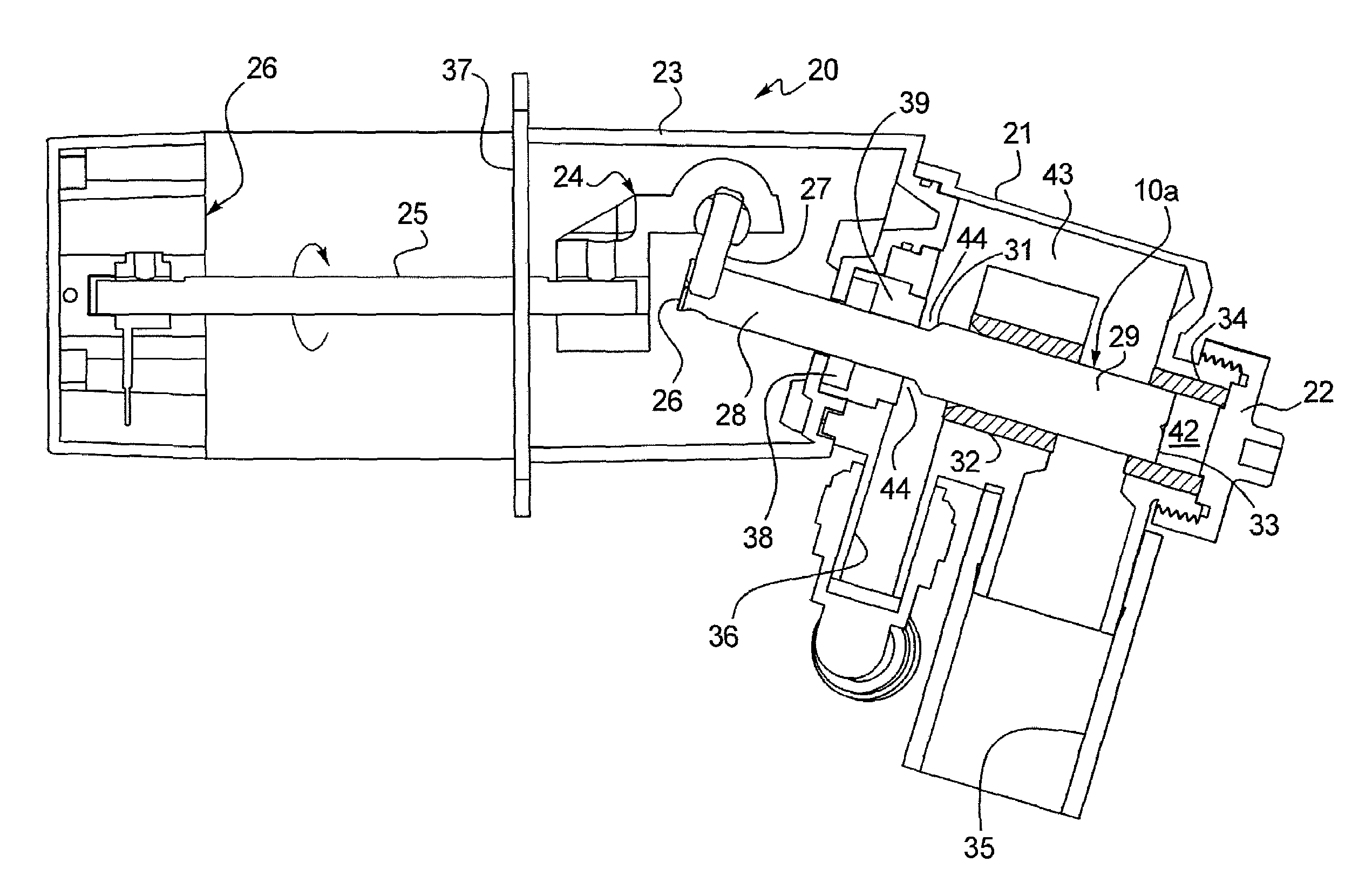
[0068]Turning to FIGS. 3A-3D, a nutating pump 20 is shown. The pump 20 includes a rotating and reciprocating piston 10A that is disposed within a pump housing 21. The pump housing 21, in the embodiment illustrated in FIGS. 3A-3B also includes an end cap or head 22. The housing or casing 21 may also be connected to an intermediate housing 23 used primarily to house the coupling 24 that connects the piston 10a to the drive shaft 25 which, in turn, is coupled to the motor shown schematically at 26. The coupling is connected to the proximal end 26 of the piston 10a b...


PUM


Abstract

A nutating pump is disclosed which has a modified piston and housing or casing that provides two distinct pump chambers or areas. Output from the first pump chamber is delivered during a first half of the dispense cycle or the piston movement cycle. A substantial portion of this output is held for delivery by the second chamber during a second part or half of the dispense cycle. Thus, the output generated by the pump is not altered or reduced, it is delivered over the entire piston movement cycle as opposed to prior art pumps which deliver all of the fluid during a first half or first portion of the piston movement cycle. In this way, superior pulse modification is achieved as fluid is delivered across the entire piston movement cycle as opposed to a first half or first portion of the piston movement cycle. In additional embodiments disclosed, two distinct chambers are also provided but each chamber generates its own output as the piston includes two machined or flat sections for active pumping. Thus, each chamber generates its own positive output flow but the flow from each chamber is delivered during a different half of the piston movement cycle. Thus, the flow is still distributed throughout the entire piston movement cycle. In the first embodiment with a first and second chamber, the second chamber essentially acts as a holding station for fluid to be delivered during a second half of the piston movement cycle.

Description

BACKGROUND[0001]1. Technical Field[0002]Improved nutating pumps are disclosed with piston designs that provide output flow in both the first and second parts of the piston rotation / reciprocation cycle thereby providing about, half the normal flow rate during the first part of the cycle as a conventional piston but also about that same flow rate during the second part of the cycle in contrast to prior art nutating pumps where there is no flow rate for second part or intake portion of the cycle. The result is smoother, reduced pulsation flow and an overall cycle dispense amount about equal to a conventional nutating pump but with less pulsations and splashing. The nutating pumps have numerous applications where accuracy and speed are important.[0003]2. Description of the Related Art[0004]Nutating pumps are pumps having a piston that both rotates about its axis liner and contemporaneously slides axially and reciprocally within a line or casing. The combined 360° rotation and reciprocat...

Claims


Application Information

Patent Timeline
Patent Type & Authority Patents(United States)
IPC IPC(8): F04B19/00F04B7/06
CPCF04B11/0075F04B7/06
Inventor HOGAN, TIM PATRICK
Owner FLUID MANAGEMENT LLC
Why Eureka
Try Eureka