Method and system for manufacturing a shear web for a wind turbine

a technology of wind turbines and shear webs, which is applied in the field of method and system for manufacturing a shear web for a wind turbine, can solve the problems of dissatisfying flow patterns and resulting structural properties of the shear web, and achieve the effect of convenient operation

Active Publication Date: 2020-01-23
LM WIND POWER US TECH APS
View PDF0 Cites 2 Cited by
  • Summary
  • Abstract
  • Description
  • Claims
  • Application Information

AI Technical Summary

Benefits of technology

[0036]Usually, after step e) the backing plates, and optionally the upper web mould part, are removed from the shear web, and the shear web in a following step is removed from the lower web mould part. This may simply be done by lifting the wind turbine component from the lower web mould ...

Problems solved by technology

This has been observed by the present inventors to result in dissatisfyi...

Method used


Image

  • Method and system for manufacturing a shear web for a wind turbine
  • Method and system for manufacturing a shear web for a wind turbine
  • Method and system for manufacturing a shear web for a wind turbine

Examples


Embodiment Construction

[0071]The invention is explained in detail below with reference to an embodiment shown in the drawings, in which

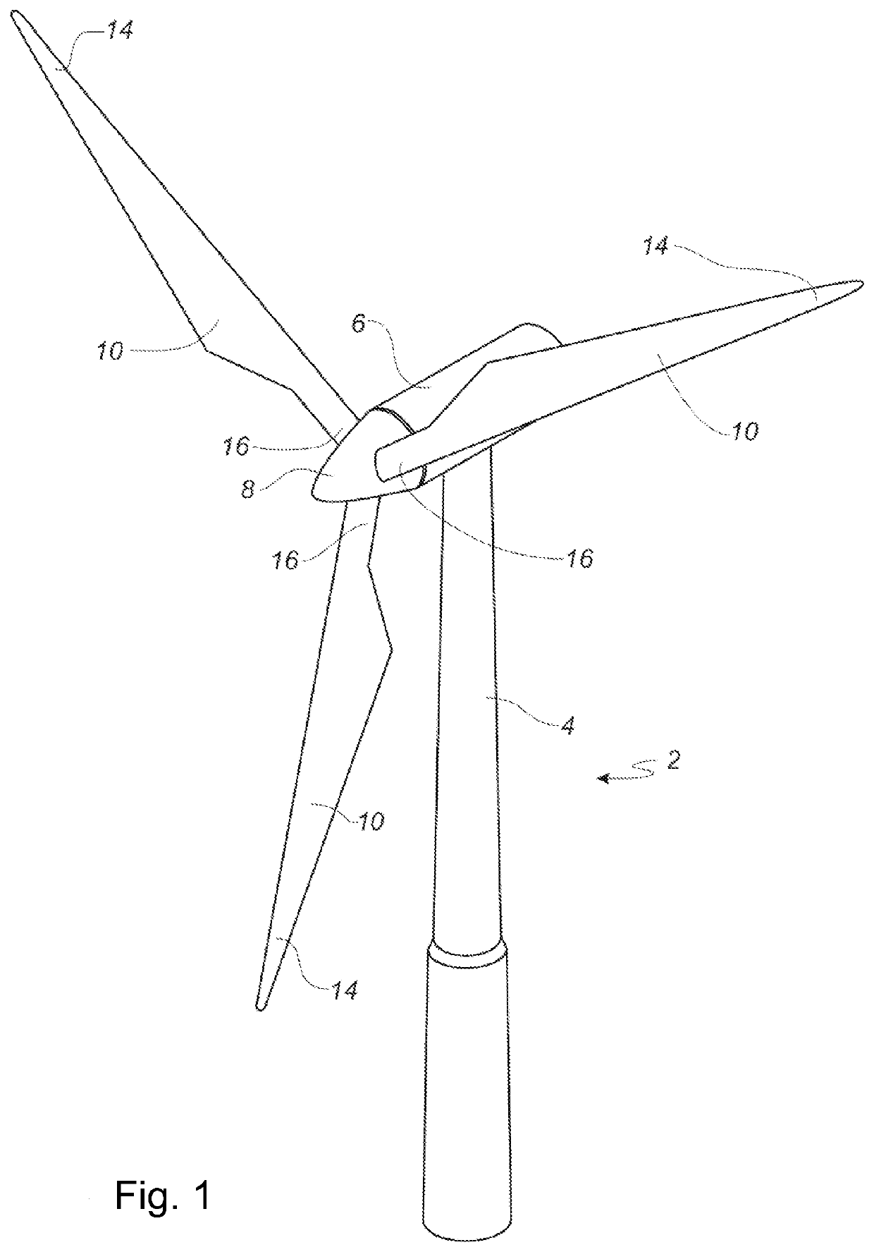
[0072]FIG. 1 shows a wind turbine,

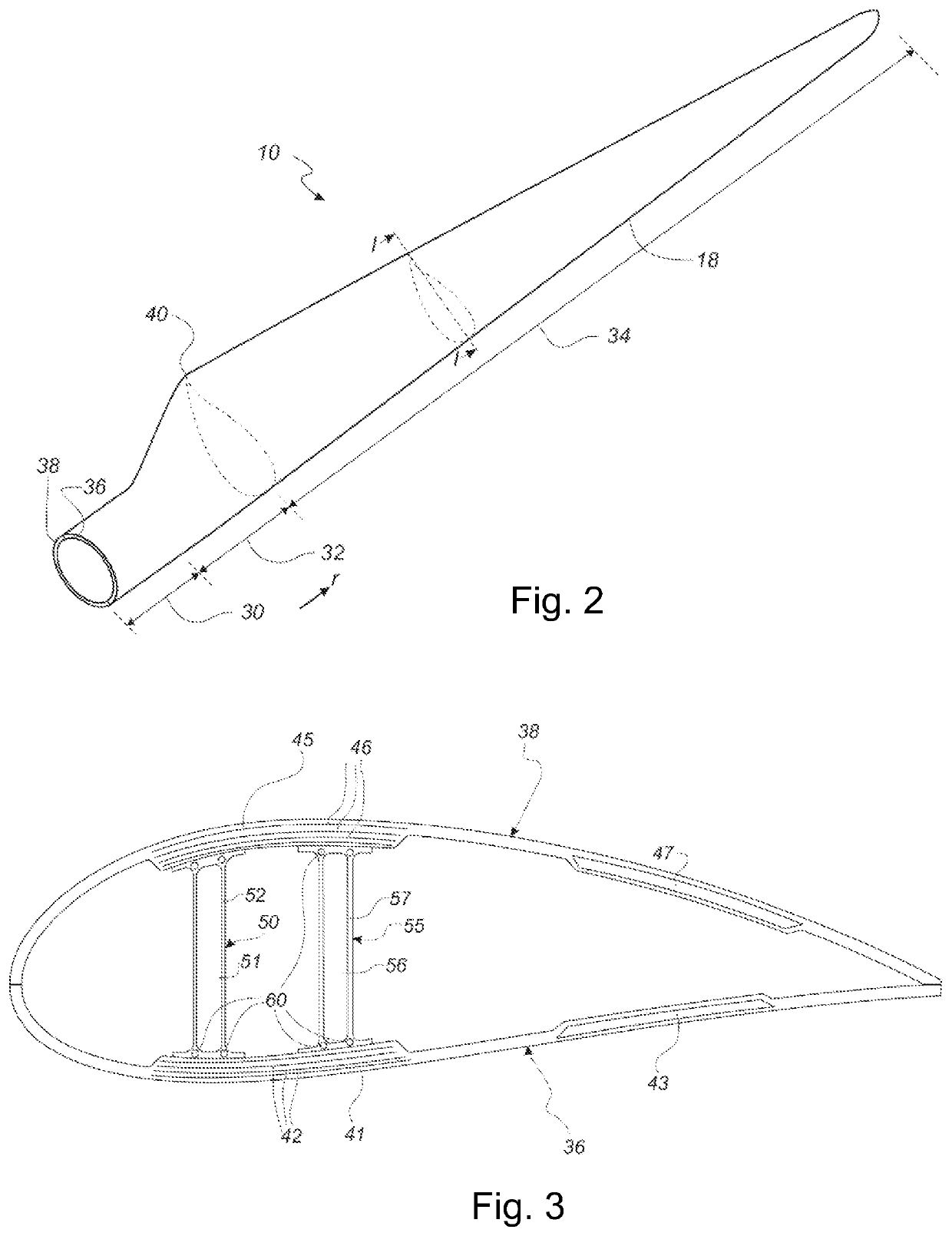
[0073]FIG. 2 shows a schematic view of a wind turbine blade,

[0074]FIG. 3 shows a schematic view of a cross-section of a wind turbine blade,

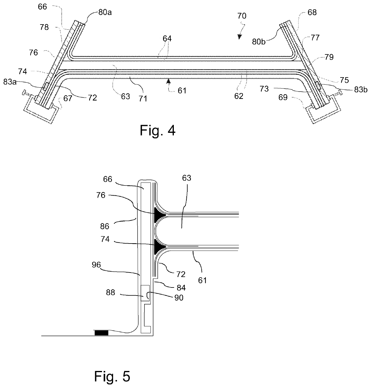
[0075]FIG. 4 shows a schematic view of a cross-section of a shear web mould system according to the present invention,

[0076]FIG. 5 shows a schematic view of a cross-section of another embodiment of a shear web mould system according to the present invention,

[0077]FIG. 6 shows a schematic view of a cross-section of another embodiment of a shear web mould system according to the present invention,

[0078]FIG. 7 shows a perspective view of a backing plate according to the present invention,

[0079]FIG. 8 shows a partially cut-away perspective view of a backing plate according to the present invention,

[0080]FIG. 9 shows a perspective view of a backing plate according to another embodiment of the present inventi...


PUM

PropertyMeasurementUnit
Widthaaaaaaaaaa
Widthaaaaaaaaaa
Widthaaaaaaaaaa

Abstract

The present invention relates to a method and to a mould system (70) for manufacturing a shear web for a wind turbine blade as well as to a backing plate (66) for such method and mould system. The method involves arranging one or more fibre layers on top of a web mould part (61), arranging backing plates (66) at each end to create a mould cavity between the first and second backing plate (66, 68) and the web mould part (61). Each backing plate (66, 68) comprises an inner moulding surface (80), outer surfaces (98, 100) and a channel (82) or groove (83) extending between at least one of the outer surfaces (98, 100) and the inner moulding surface (80). Resin is supplied to the mould cavity via each channel or groove of the first and second backing plate (66, 68), and subsequently the resin is cured or hardened to form the shear web.

Description

FIELD OF THE INVENTION[0001]The present invention relates to a method and to a mould system for manufacturing a shear web for a wind turbine blade as well as to a backing plate for such method and mould system.BACKGROUND OF THE INVENTION[0002]Wind turbine blades are often manufactured according to one of two constructional designs, namely a design where a thin aerodynamic shell is glued or otherwise bonded onto a spar beam, or a design where spar caps, also called main laminates, are integrated into the aerodynamic shell.[0003]In the first design, the spar beam constitutes the load bearing structure of the blade. The spar beam as well as the aerodynamic shell or shell parts are manufactured separately. The aerodynamic shell is often manufactured as two shell parts, typically as a pressure side shell part and a suction side shell part. The two shell parts are glued or otherwise connected to the spar beam and are further glued to each other along a leading edge and trailing edge of th...

Claims


Application Information

Patent Timeline
IPC IPC(8): B29C33/00B29C70/44B29C70/54
CPCB29D99/0003B29C33/0066B29C70/443B29L2031/085B29C70/548Y02P70/50Y02E10/72
Inventor SCHIBSBYE, KARSTENLARSEN, MICHAELMADSEN, KRISTIAN LEHMANN
Owner LM WIND POWER US TECH APS
Why Eureka
Try Eureka