Condensing skeletal implant that facilitate insertions

a skeletal implant and condensing technology, applied in the field of bone anchorage implants, can solve the problems of difficult control of the implant position, difficult to achieve the stability of the dental implant in low-density bone, and difficulty in condensing the insertion

Active Publication Date: 2007-05-03
NOBEL BIOCARE SERVICES AG
View PDF24 Cites 80 Cited by
  • Summary
  • Abstract
  • Description
  • Claims
  • Application Information

AI Technical Summary

Benefits of technology

[0038] According to a further feature of the present invention, the apical end includes at least one segment having a tapered variable profile helical thread extending along the core, the thread having an apical side, a coronal side, a lateral edge connecting the apical side and the coronal side, a base touching the core, a height defined between the lateral edge and the base, a variable length of the lateral edge being progressively expanded substantially along the segment of the apical end in the direction of the coronal end, so that a least length of the lateral edge of the thread is adjacent the apical end and a greatest length of the lateral edge of the thread is adjacent the coronal end, and a variable height being progressively expanded substantially along the segment of the implant in the direction of the apical end, so that a least height of the thread is adjacent the coronal end and a greatest height of the thread is adjacent the apical end.

Problems solved by technology

Dental implant stability in low-density bone, such as that found in the posterior regions of the mandible and maxilla and in regenerated bone, can be difficult to achieve.
As an implant is designed to be more condensing its insertion becomes more difficult.
It is also more difficult to control the position of the implant since a condensing implant has a stronger tendency to slip into a region with the lowest bone density.

Method used


Image

  • Condensing skeletal implant that facilitate insertions
  • Condensing skeletal implant that facilitate insertions
  • Condensing skeletal implant that facilitate insertions

Examples


Embodiment Construction

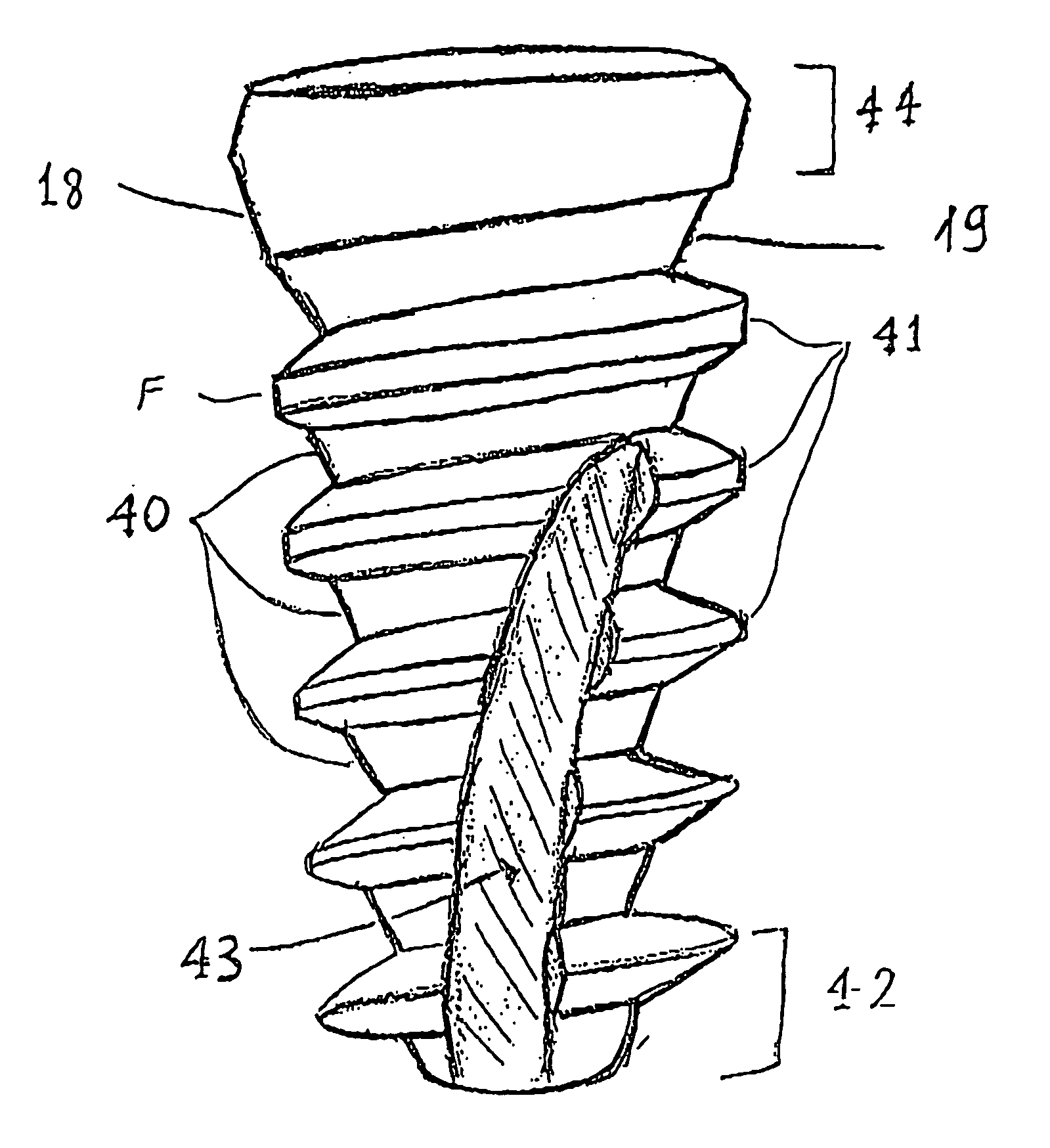
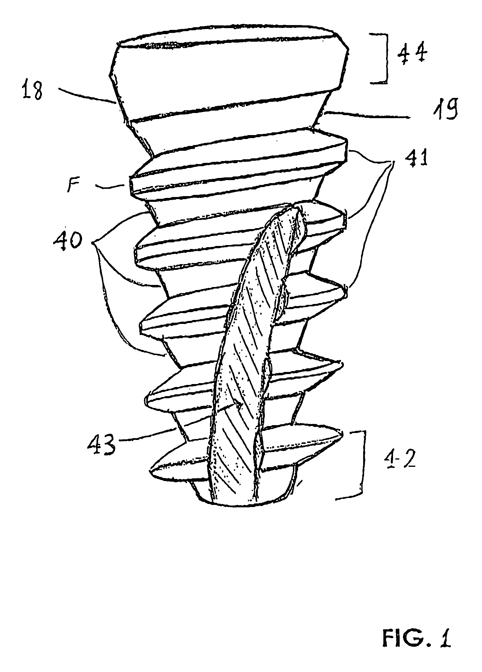
[0096]FIG. 1 illustrates an embodiment of the novel tapered condensing dental implant. There are five elements in a dental implant that influence the condensation, insertion and stabilization of the implant. 1) The core of the implant 40. 2) The Threads 41. 3) The most apical region 42 which touches the bone first. 4) The bone tap 43. 5) The most coronal region 44 which engages the cortical bone and the sometimes also the gums.

[0097] In order to have good stabilization in low density bone it is recommended to use small diameter drill and tapered implant. As the diameter of the drill is smaller and the implant is more tapered the bone is more preserved and more condensed resulting in improved stabilization, but the insertion is more difficult. In this case controlling the exact path of insertion of the implant becomes also more difficult since the implant has a tendency to slip towards the region with the lowest density. In order to use a small diameter drill and an implant with sig...


PUM


Abstract

A dental implant that facilitates insertion includes a body having a coronal end (44) and an apical end (42) opposite the coronal end (44). An implant-prosthetic interface region (16) is provided adjacent the coronal end (44). A tapered region (22) is adjacent the apical end (42). A variable profile helical thread (41) extends along the tapered region (22). The thread (41) becomes broader in the apical-coronal direction and higher in the coronal-apical direction. The threads (41) include and apical side (A), a coronal side (C) and a lateral edge (T) connecting them. The variable profile thread (41) includes an expanding length of the lateral edge (T) while the distance of the lateral edge (T) from the base is reduced in the direction of the coronal end (44). The implant also has a gradual compressing tapered core (40), a self drilling apical end (42) with a spiral tap, and a coronal end (44) with and inverse tapering.

Description

FIELD AND BACKGROUND OF THE INVENTION [0001] The disclosures herein relate generally to bone anchorage implants and more particularly to a screw form dental implant having a combination of features designed to produce bone condensation while insertion is easy. [0002] Many current screw-form dental implants are well designed for use in dense bone. For example, the implant disclosed in U.S. Pat. No. 5,897,319 has sharp cutting features at their apical ends that readily facilitate self-tapping into hard bone. [0003] The osseous anatomy of the human jaw is complex. While the density of the bone in the anterior regions of the mandible and maxilla is high, the posterior regions, particularly in the maxilla, are of significantly lower density. The height of the bony ridge in the posterior maxilla can be greatly reduced in partially or totally edentulous patients. This can lead to the need for use of shorter dental implants or grafting procedures in order to increase the height of bone avai...

Claims


Application Information

Patent Timeline
Patent Type & Authority Applications(United States)
IPC IPC(8): A61C8/00
CPCA61C8/0022A61C8/0025A61C8/0075A61C8/0077A61C8/0066A61C8/0069A61C8/005A61C8/0045A61C8/0024
Inventor FROMOVICH, OPHIR
Owner NOBEL BIOCARE SERVICES AG
Why Eureka
Try Eureka