Device for releasably clamping a longitudinal member within a surgical implant

a technology for surgical implants and longitudinal members, applied in the field of releasably clamping and connecting a longitudinal member within a surgical implant, can solve the problems of great rigidity of the implant as a whole, and achieve the effect of preventing the connection of the rod and great rigidity

Inactive Publication Date: 2005-03-15
SYNTHES USA
View PDF21 Cites 88 Cited by
  • Summary
  • Abstract
  • Description
  • Claims
  • Application Information

AI Technical Summary

Benefits of technology

Advantageously, the device of the present invention prevents slipping of the rod connection after implantation, due to the force acting on the longitudinal member. In addition, the device of the present invention permits the connection of longitudinal members which are not implanted in parallel. Further, even when the device is subjected to significant torques such as by the longitudinal member or members, the implant as a whole has great rigidity.
Thus, the clamping body can be brought into a first position in relation to the connecting body which allows the side walls to spring out transversely with respect to the central axis, so that a longitudinal member can be snapped into the through-opening coaxially with respect to the central axis. By tightening the fixation means, the clamping body can be brought into a second position, so that the cross section of the through-opening is reduced by at least one of the parts moved in relation to the clamping body to such an extent that a longitudinal member placed in the through-opening is pressed against the elevations. A wedging effect is thus produced on the elevations, and the side walls of the clamping body are pressed against the inner sides of the side walls of the connecting body.
The fixation means is advantageously designed in such a way that a tensile force can be exerted on the clamping body from the end of the connecting body on the fixation means side. For this purpose, the clamping body is for example provided at its end on the fixation means side with an internal thread running coaxially with respect to the central axis, and the fixation means is formed as a locking screw with an external thread corresponding to the internal thread and the screw head of which at the end of the connecting body on the fixation means side is secured against movement in the direction of the central axis. The securing of the screw head is possible by mounting the screw head or a flange-shaped part thereof in a relief in the through-bore of the connecting body. As a result, the locking screw is secured against movements in the axial direction and continues to be freely rotatable.
The through-opening preferably has a circular-cylindrical core with a diameter D, while the side faces bounding the elevations towards the through-opening have a distance A at right angles with respect to the central axis. The ratio A / D is between about 85% and about 98%, preferably between about 92% and about 98%. This configuration of the through-opening makes it possible, by the resilient side walls of the clamping body, for the longitudinal member to be snapped in and for the longitudinal member to be stable and fixed in the through-opening when the locking screw is tightened.
In order that the longitudinal member can be inserted more easily into the through-opening from the entry in the direction of the central axis, the free ends of the clamping body may also be provided with centering jaws which are designed in such a way that the cross-section of the through-opening narrows from the entry at the free ends towards the elevations, thus making it possible for a longitudinal member to be centered and inserted into the through-opening in a simple manner. The centering jaws may taper toward the free ends in planes running parallel to a plane defined by the central axis and the longitudinal axis.

Problems solved by technology

Further, even when the device is subjected to significant torques such as by the longitudinal member or members, the implant as a whole has great rigidity.

Method used


Image

  • Device for releasably clamping a longitudinal member within a surgical implant
  • Device for releasably clamping a longitudinal member within a surgical implant
  • Device for releasably clamping a longitudinal member within a surgical implant

Examples


Embodiment Construction

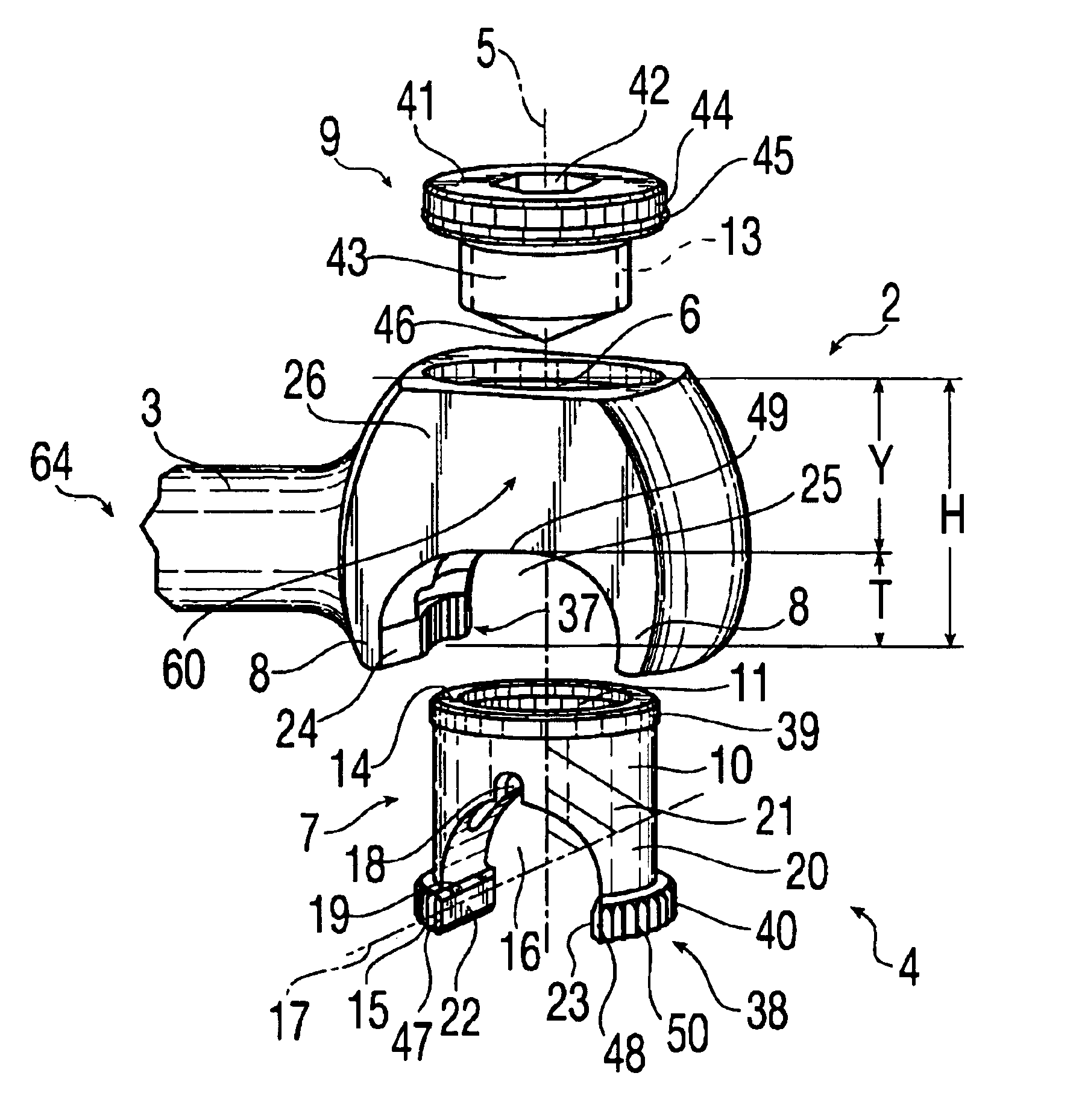
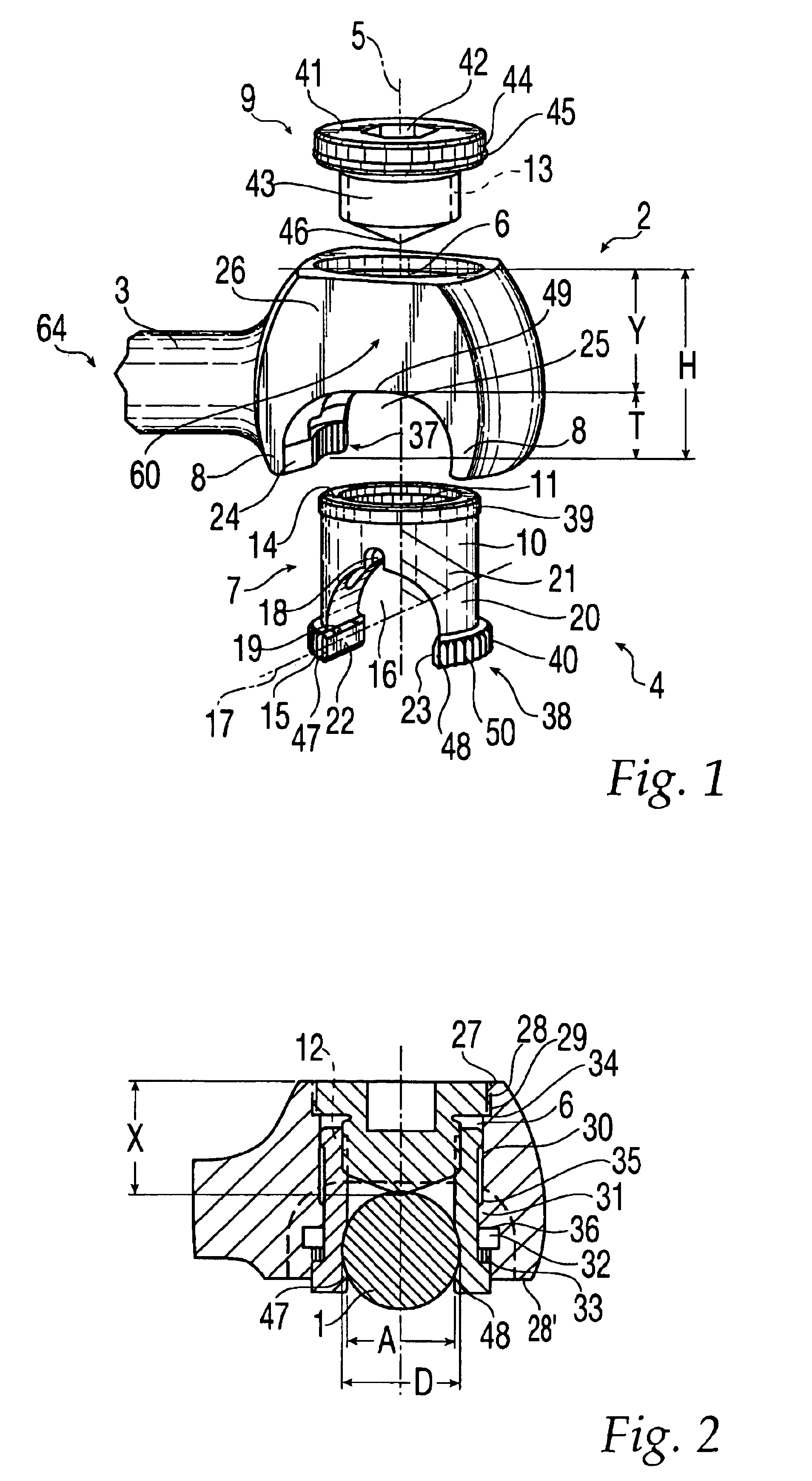
With reference to FIGS. 1 and 2, an exemplary embodiment of a device according to the present invention is shown including a connecting element 4 between a longitudinal member 1 and a transverse rod 3. In this exemplary embodiment, connecting element 4 comprises a yoke-like connecting body 2 that is symmetrical with respect to a central axis 5 and has a through-bore 6 coaxially disposed on central axis 5. Connecting element 4 also includes a hollow-cylindrical clamping body 7 which is displaceable in through-bore 6 parallel to central axis 5, and a fixation means 9 for fixing longitudinal member 1 within the device.

Yoke-like connecting body 2 includes two side walls 8 that may run in the direction of central axis 5. A free space 25 is disposed between side walls 8, which have side faces 24 that are angulated to converge toward through-bore 6. As such, a longitudinal member 1 passing through free space 25 can be fastened within an angular range of between about 75° and about 105° wit...


PUM


Abstract

A device for releasably clamping and connecting a longitudinal member within a surgical implant includes at least one yoke-like connecting body with a through-bore, coupling means arranged on the connecting body for fastening the connecting body to a further part of the implant, a yoke-like clamping body which can slide in the through-bore and has resilient side walls and a through-opening for receiving the longitudinal member, and fixation means. A wedging effect produced by elevations on side walls of the clamping body retains the longitudinal member in the through-opening.

Description

FIELD OF THE INVENTIONThe invention relates to a device for releasably clamping and connecting a longitudinal member within a surgical implant in the body of human or animal.BACKGROUND OF THE INVENTIONSurgical implants as used for bone fixation or specifically for spinal fixation often contain one or more longitudinal members, to which the bone fixation elements or, specifically in the case of spinal fixation, the pedicle screws are fastened and consequently are fixed with respect to one another in a longitudinal direction. For stiffening an implant as a whole, containing a plurality of longitudinal members, the longitudinal members are connected to one another by means of transverse connectors, which are attached transversely with respect to the longitudinal members between the latter.Some devices for connecting longitudinal members within spinal column implants are already known from the prior art. These have the advantage that the implanted longitudinal members are considerably s...

Claims


Application Information

Patent Timeline
Patent Type & Authority Patents(United States)
IPC IPC(8): A61B17/70A61BA61B17/56A61B17/58A61F2/30
CPCA61B17/7052
Inventor SCH.ANG.R, MANUELGERBER, DAVIDSCHL.ANG.PFER, FRIDOLIN
Owner SYNTHES USA
Why Eureka
Try Eureka