System and methods for restoring the structural integrity of bone

a structural integrity and bone technology, applied in the field of bone structural integrity restoration, can solve the problems of weakened spinal column stability, affecting the function of the bone, so as to encourage the reformation of the lamina

Inactive Publication Date: 2005-05-19
NUVASIVE
View PDF42 Cites 86 Cited by
  • Summary
  • Abstract
  • Description
  • Claims
  • Application Information

AI Technical Summary

Benefits of technology

[0012] The present invention accomplishes this goal by providing a stabili

Problems solved by technology

While this operation can be successful in solving the immediate problem (pain in the back, arms, or legs), the procedure itself creates its own set of problems.
Removal of the lamina and sipnous process can weaken the stability of the spinal column, especially in elderly patients.
This is especially unfortunate because the scar tissue in effect puts pressure on the nerve that the surgical procedure was designed to alleviate.
Patients undergoing ACDF may experience temporary hoarseness and difficulty swallowin

Method used


Image

  • System and methods for restoring the structural integrity of bone
  • System and methods for restoring the structural integrity of bone
  • System and methods for restoring the structural integrity of bone

Examples


embodiment 110

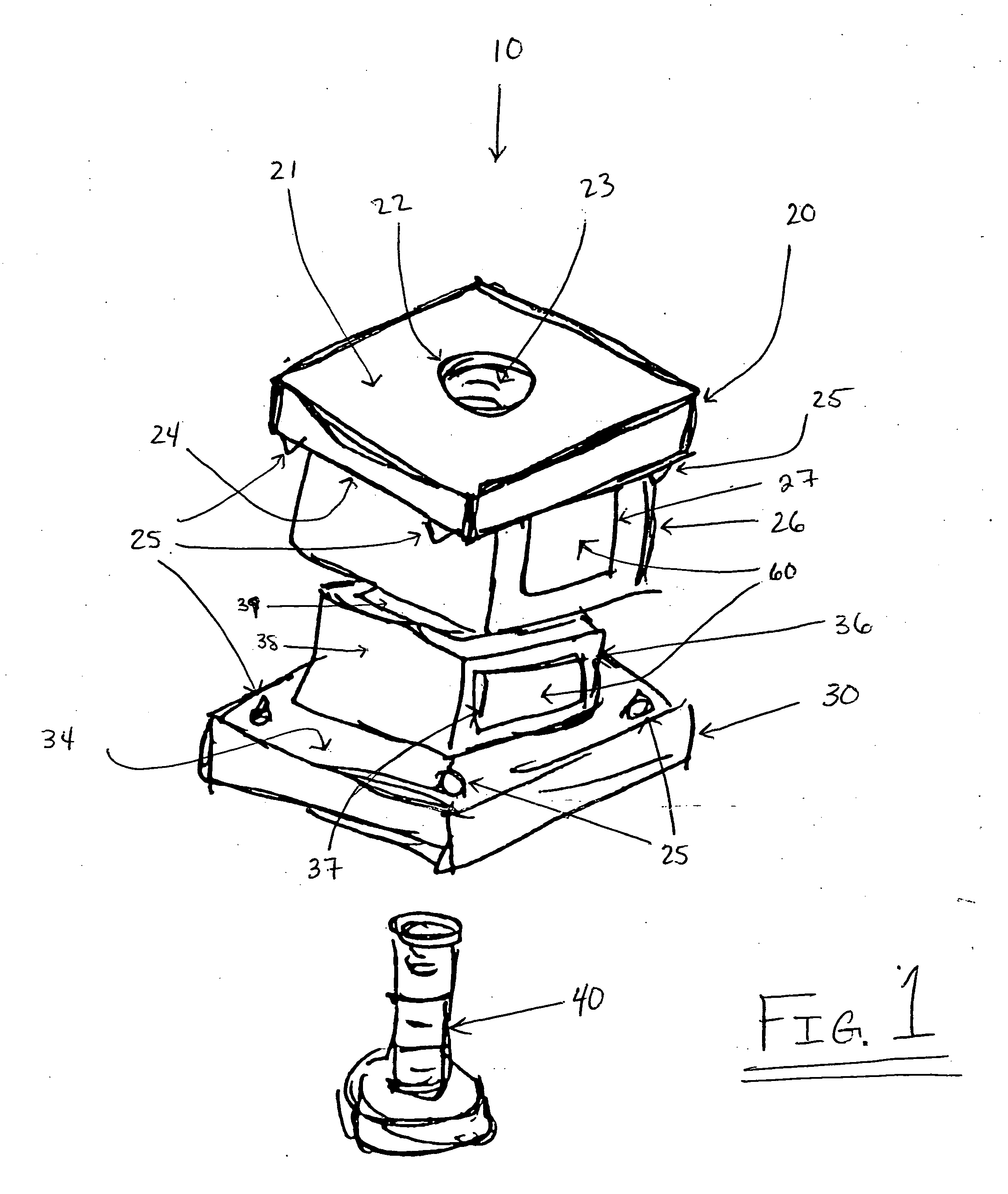
[0027]FIG. 4 represents an alternative embodiment 110 of the laminoplasty device 10 of the present invention. The laminoplasty device 110 includes a superior attachment panel 120, an inferior base panel 130, and a coupling screw 140. The superior attachment peel 120 includes a bore 122 that, in a preferred embodiment, includes threads (not shown). Bore 122 is located in a relatively central location of superior latitudinal surface 121 of superior attachment panel 120. Through bore 122 passes coupling screw 140, which when attached with inferior base panel 130 will securely hold together the fully assembled laminoplasty device 110. Inferior latitudinal surface 124 of superior attachment panel 120 may contain spikes (not shown) located, in a preferred embodiment, at each of four corners of the superior attachment panel 120. It is contemplated that in alternative embodiments of laminoplasty device 110, in which the shape of superior attachment panel 120 is other than rectangular or squ...

embodiment 210

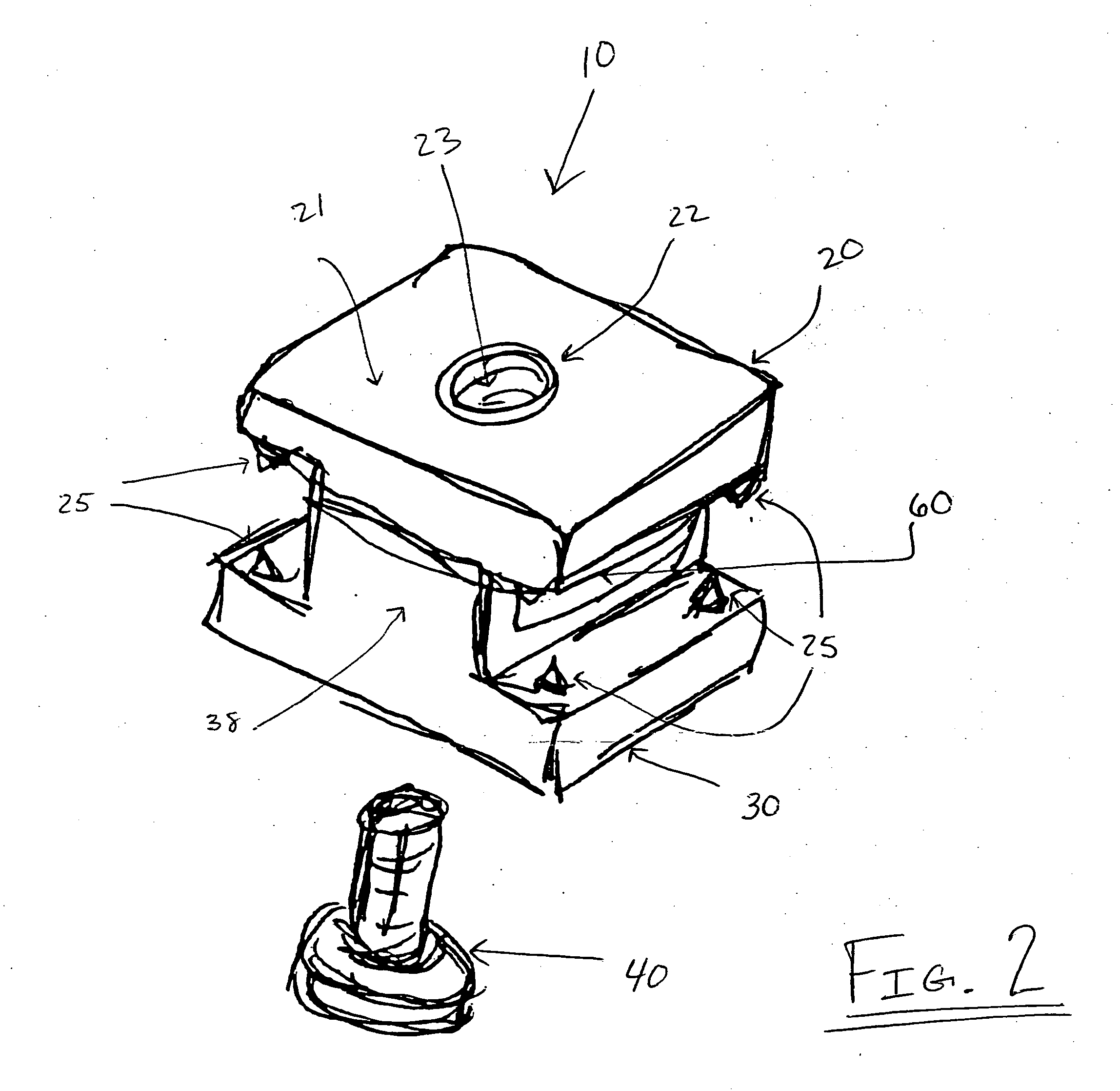
[0031]FIG. 5 represents an alternative embodiment 210 of the laminoplasty device 10 of the present invention. The laminoplasty device 210 includes a superior attachment panel 220, an inferior base panel 230, and a coupling screw 240 (not shown). The superior attachment panel 220 includes a bore 222 that, in a preferred embodiment, includes threads 223. Bore 222 is located in a relatively central location of superior latitudinal surface 221 of superior attachment panel 220. Through bore 222 passes coupling screw 240 (not shown), which when attached with inferior base panel 230 will securely hold together the fully assembled laminoplasty device 210. Inferior latitudinal surface 224 of superior attachment panel 220 may contain spikes 225 located, in a preferred embodiment, at each of four corners of the superior attachment panel 220. It is contemplated that in alternative embodiments of laminoplasty device 210, in which the shape of superior attachment panel 220 is other than rectangul...


PUM


Abstract

A laminoplasty device including a superior attachment panel, inferior base panel, and a coupling screw for use in repair of lamina after spinal surgery. The interior of the fully assembled laminoplasty device contains a fusion corridor in which bone fusion material can be placed to facilitate regeneration of the lamina.

Description

CROSS REFERENCES TO RELATED APPLICATIONS [0001] The present application is a nonprovisional patent application claiming benefit under 35 U.S.C. § 119(e) from U.S. Provisional Application Ser. No. 60 / 516,946, filed on Oct. 30, 2003, the entire contents of which are hereby expressly incorporated by reference into this disclosure as if set forth fully herein.BACKGROUND OF THE INVENTION [0002] I. Field of the Invention [0003] The present invention relates generally to restoring the structural integrity of bone and more particularly, to repair and fusion of the lamina after spinal surgery. [0004] II. Discussion of the Prior Art [0005] Spinal stenosis is a condition in which the spinal canal has been narrowed or structured, and although it is a problem that occurs mostly in the aging population, it can also affect younger persons who have experienced certain types of trauma. The causes of spinal stenosis are many, but a partial list includes congenital stenosis, bone spurs, intervertebral...

Claims


Application Information

Patent Timeline
IPC IPC(8): A61B17/70A61F2/00A61F2/28A61F2/30
CPCA61B17/7071A61F2310/00359A61F2/2846A61F2002/2835A61F2002/30153A61F2002/30154A61F2002/30166A61F2002/30263A61F2002/30271A61F2002/30382A61F2002/30433A61F2002/30434A61F2002/30601A61F2002/30622A61F2002/30772A61F2002/30774A61F2002/30785A61F2002/30789A61F2002/30841A61F2002/30892A61F2220/0033A61F2220/0041A61F2230/0019A61F2230/0021A61F2230/0028A61F2230/0082A61F2230/0084A61F2310/00017A61F2310/00179A61F2/28A61F2002/30261A61F2002/30331A61F2002/30593
Inventor BLAIN, JASON
Owner NUVASIVE
Why Eureka
Try Eureka