Continuously variable planetary gear set

a planetary gear set, continuous technology, applied in the direction of gearing, mechanical equipment, transportation and packaging, etc., can solve the problems of difficult shifting of the axis of rotation of each of the traction rollers, the success of traditional solutions is limited, and the use of iris plates can be very complicated

Active Publication Date: 2004-11-11
FALLBROOK INTPROP COMPANY
View PDF99 Cites 91 Cited by
  • Summary
  • Abstract
  • Description
  • Claims
  • Application Information

AI Technical Summary

Benefits of technology

[0045] The input disc 34 and the output disc 101 can be shaped as simple discs or can be concave, convex, cylindrical or any other shape, depending on the configuration of the input and output desired. In one embodiment, the input and output discs 34, 101 are spoked to make them lighter for weight sensitive applications, to allow ease of assembly by providing one or more openings wherein access is provided through the input or output disc 34, 101, and to allow fluid, such as lubricant and / or coolant to flow through input and output discs 34, 101. The rolling contact surfaces of the discs 34, 101 where they engage the speed adjuster balls 1 can have a flat, concave, convex or other shaped profile, depending on the torque and efficiency requirements of the application. A concave profile where the discs 34, 101 contact the balls 1 decreases the amount of axial force required to prevent slippage while a convex profile increases efficiency. In some embodiments the contact surface of each of the input and output discs 34, 101 is a separate replaceable component that can be easily removed and replaced. In such embodiments, the contact surface can be a ring made of the appropriate material that is threaded into the rest of the input or output disc 34, 101, while in other embodiments the contact surface has a flange or other attachment surface and is attached by fasteners. The variator 401 embodiment shown in FIG. 7 illustrates an input disc 34 having an input disc 34 that utilizes a separate and detachable disc ring 3401 attached by such a flange assembly. The disc ring 3401 shown in this figure attaches to the input disc 34 via a flange and fastener assembly 3402 consisting of a disc ring flange (not separately identified) that extends from the outer surface of the disc ring 3401, a disc flange (not separately identified) that extends from outer surface of the input disc 34, disc ring fasteners (not separately identified) that connect the disc ring flange to the disc flange and a locating section 3403 that can be used by some embodiments to precisely control the position of the disc ring 3401 with respect to the input disc 34. The locating section 3403 of the illustrated embodiment is made of an outward facing edge formed on the disc ring flange and an inward facing edge formed on the input disc flange, the two of which cooperate to accurately control the radial and axial position of the disc ring 3401 with respect to the input disc 34. The use of the separate contact surface, such as the disc ring 3401 of FIG. 7, reduces cost by allowing for replacement of the contact surface alone while it also allows for the use of less expensive materials for the rest of the input and output discs 34, 101.
[0088] The iris rollers 407 are radiused along their outside diameters, or have fillets on their outer corners, so that their diameters remain unchanged inside the grooves 411 of the iris plate 409 when the ball axles 433 are tilted. The iris plate 409 is of a thickness sufficient to allow iris rollers 407 from both variators 420, 422, to remain inside the grooves 411 of the iris plate 433 at all shifting ratios. The iris grooves 411 operate in traditional iris plate fashion and cause the ball axles 433 to move radially inward or outward when the iris plate 409 is rotated. The iris plate 409 has a first side facing the first variator and a second side facing the second variator and is coaxially positioned about the longitudinal axis 11 of the transmission 1700 and over abutting bosses on tubular extensions extending from the two output stators 435. The two output stators 435 can be attached to each other with conventional fasteners through axial holes (not illustrated) in the bosses of the output stators 435. The output stator 435 bosses have a hole through their centers and multiple holes positioned radially outward from the center. In some embodiments, the bosses on the output stators 435 form a space slightly wider than the iris plate 409 to provide freedom of rotation for the iris plate 433 and some embodiments utilize bearings between the bosses and the iris plate 409 to accurately control the position of the iris plate 409 between the output stators 435. An iris cable 406 is attached to the first side of the iris plate 409 near the outside diameter of the iris plate 409 and extends longitudinally from the point of connection.

Problems solved by technology

However, the success of these traditional solutions has been limited.
However, the use of iris plates can be very complicated due to the large number of parts that are required to adjust the angular position of the iris plates during shifting of the transmission.
Another difficulty with this transmission is that it has a guide ring that is configured to be predominantly stationary in relation to each of the rollers.
Since the guide ring is stationary, shifting the axis of rotation of each of the traction rollers is difficult.
A key limitation of this design and improvements of this design is the absence of means for generating and adequately controlling the axial force acting as normal contact force to keep the input disc and output disc in sufficient frictional contact against the balls as the speed ratio of the transmission changes.
This excessive axial force lowers efficiency and causes the transmission to fail significantly faster than if the proper amount of force was applied for any particular gear ratio.
The excessive force also makes it more difficult to shift the transmission.

Method used


Image

  • Continuously variable planetary gear set
  • Continuously variable planetary gear set
  • Continuously variable planetary gear set

Examples


Embodiment Construction

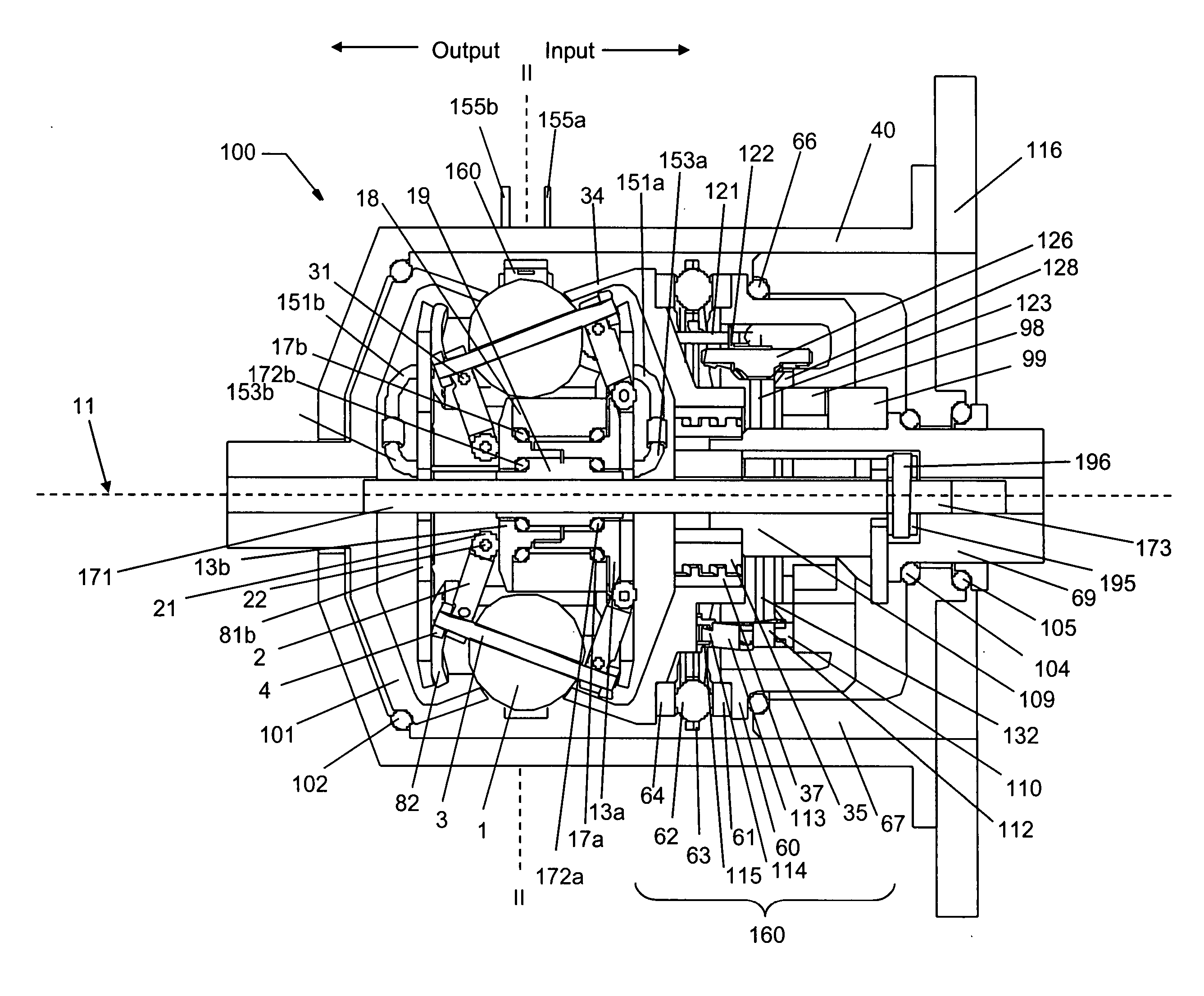
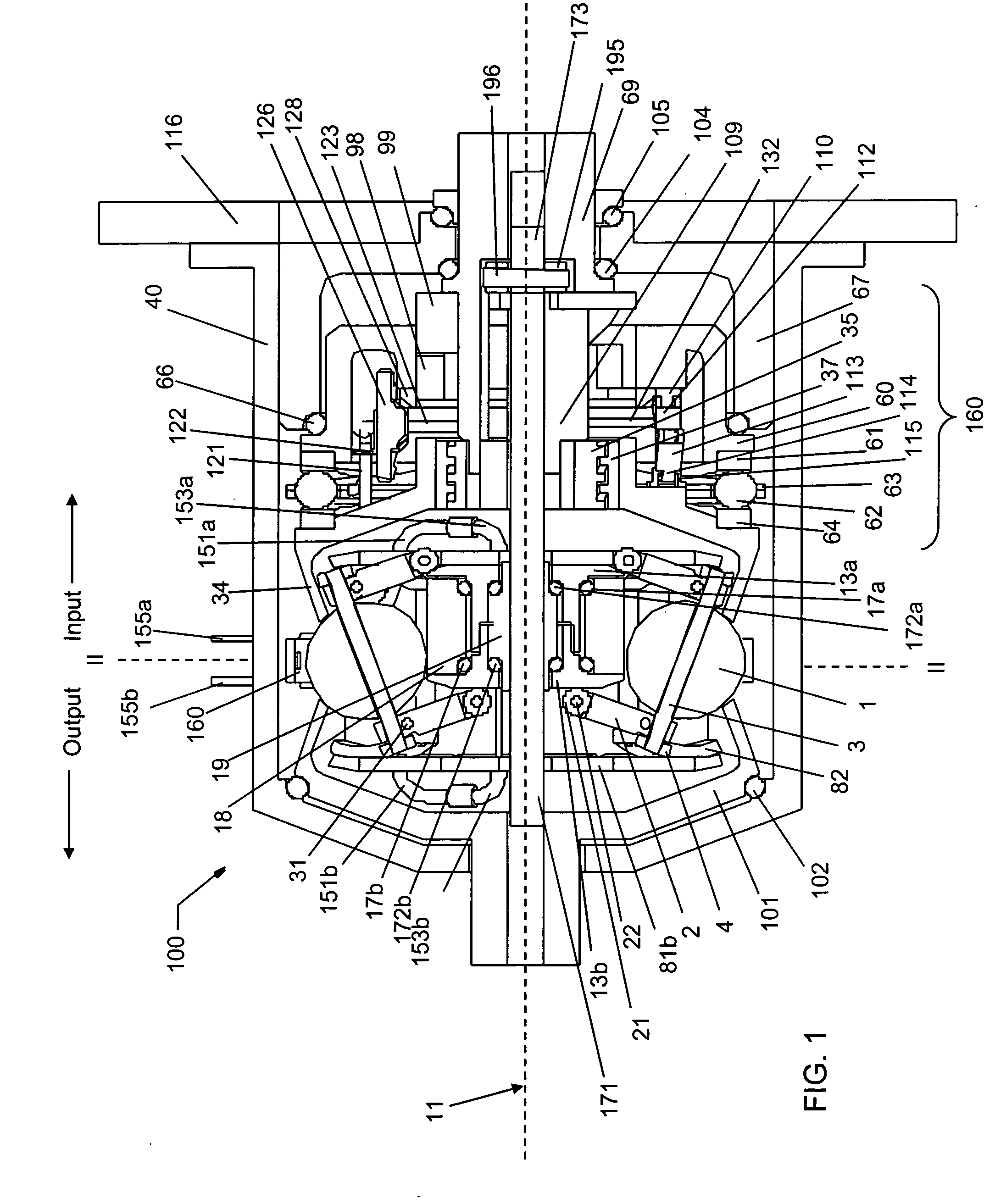
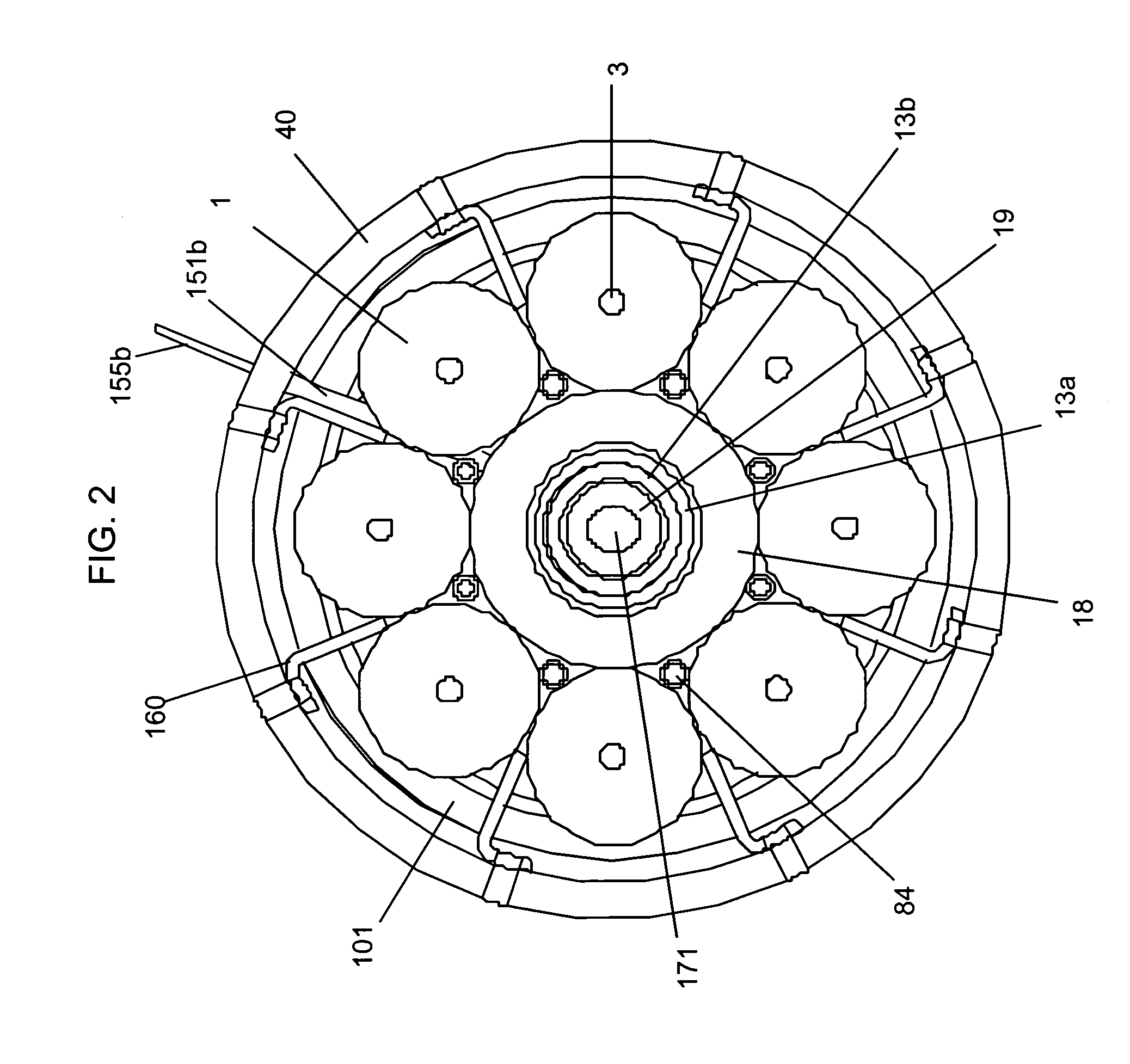
[0092] Each of the variations that will now be described may have advantageous characteristics for particular applications. The variations can be modified and controlled as necessary to achieve the goals for any particular application. Specific embodiments will now be described and illustrated that employ some of the variations described herein and / or listed in the Tables provided in U.S. patent application Ser. No. 10 / 788,736, which were incorporated above by reference. FIGS. 11 and 12 illustrate one embodiment of a transmission 1100 that is a variation having one source of torque input and that supplies two sources of torque output. As before, only the significant differences between the embodiment illustrated in FIGS. 11 and 12 and the previously illustrated and described embodiments will be described. Furthermore, the components illustrated are being provided to illustrate to one of skill in the art how to provide power paths and torque output sources that have not been previous...


PUM


Abstract

A continuously variable planetary gear set is described having a generally tubular idler, a plurality of balls distributed radially about the idler, each ball having a tiltable axis about which it rotates, a rotatable input disc positioned adjacent to the balls and in contact with each of the balls, a rotatable output disc positioned adjacent to the balls opposite the input disc and in contact with each of the balls such that each of the balls makes three-point contact with the input disc, the output disc and the idler, and a rotatable cage adapted to maintain the axial and radial position of each of the balls, wherein the axes of the balls are oriented by the axial position of the idler.

Description

[0001] This application claims priority to U.S. Provisional Application No. 60 / 494,376 filed Aug. 11, 2003, U.S. Provisional Application No. 60 / 512,600 filed Oct. 16, 2003, U.S. Provisional Application 60 / 537,938 filed Jan. 21, 2004 and U.S. patent application Ser. No. 10 / 788,736, filed Feb. 26, 2004, and all of these applications are hereby incorporated by reference in their entireties.[0002] 1. Field of the Invention[0003] The field of the invention relates generally to transmissions, and more particularly the invention relates to continuously variable planetary gear sets that can be used in transmissions as well as other industrial and land, air and water-borne vehicles.[0004] 2. Description of the Related Art[0005] In order to provide a continuously variable transmission, various traction roller transmissions, in which power is transmitted through traction rollers supported in a housing between torque input and output discs, have been developed. In such transmissions, the tracti...

Claims


Application Information

Patent Timeline
Patent Type & Authority Applications(United States)
IPC IPC(8): B62D5/04B62M9/08F16H15/28F16H15/40F16H15/52F16H37/08F16H61/664
CPCB62D5/0409Y10S903/918B62M9/08F16H15/28F16H15/52F16H37/084F16H61/6649Y10T477/33Y10T74/19251Y10T477/619Y10T477/688Y10T477/679Y10T477/23Y10T74/19555Y10T74/1956Y10T477/621Y10S903/951Y10S903/945B62D5/0475
Inventor MILLER, DONALD C.ALLEN, DAVID J.SMITHSON, ROBERT A.BIRCHAK, JEFFREY A.
Owner FALLBROOK INTPROP COMPANY
Why Eureka
Try Eureka