Mechanism and method of controlling an automatic shifting power transmission to effect a first gear launch

a technology of automatic shifting and power transmission, which is applied in the direction of gear control, gearing elements, gearing, etc., can solve the problems of reducing the stall speed of the converter, so as to reduce the stall speed and improve the efficiency, the effect of negligible impact on the launch performan

a technology of automatic shifting and power transmission, which is applied in the direction of gear control, gearing elements, gearing, etc., can solve the problems of reducing the stall speed of the converter, so as to reduce the stall speed and improve the efficiency, the effect of negligible impact on the launch performan

US20070021266A1Inactive Publication Date: 2007-01-25GM GLOBAL TECH OPERATIONS LLC

Image

  • Mechanism and method of controlling an automatic shifting power transmission to effect a first gear launch
  • Mechanism and method of controlling an automatic shifting power transmission to effect a first gear launch
  • Mechanism and method of controlling an automatic shifting power transmission to effect a first gear launch

Examples


Embodiment Construction

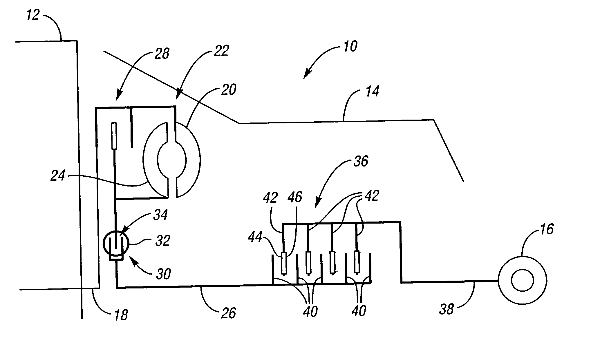
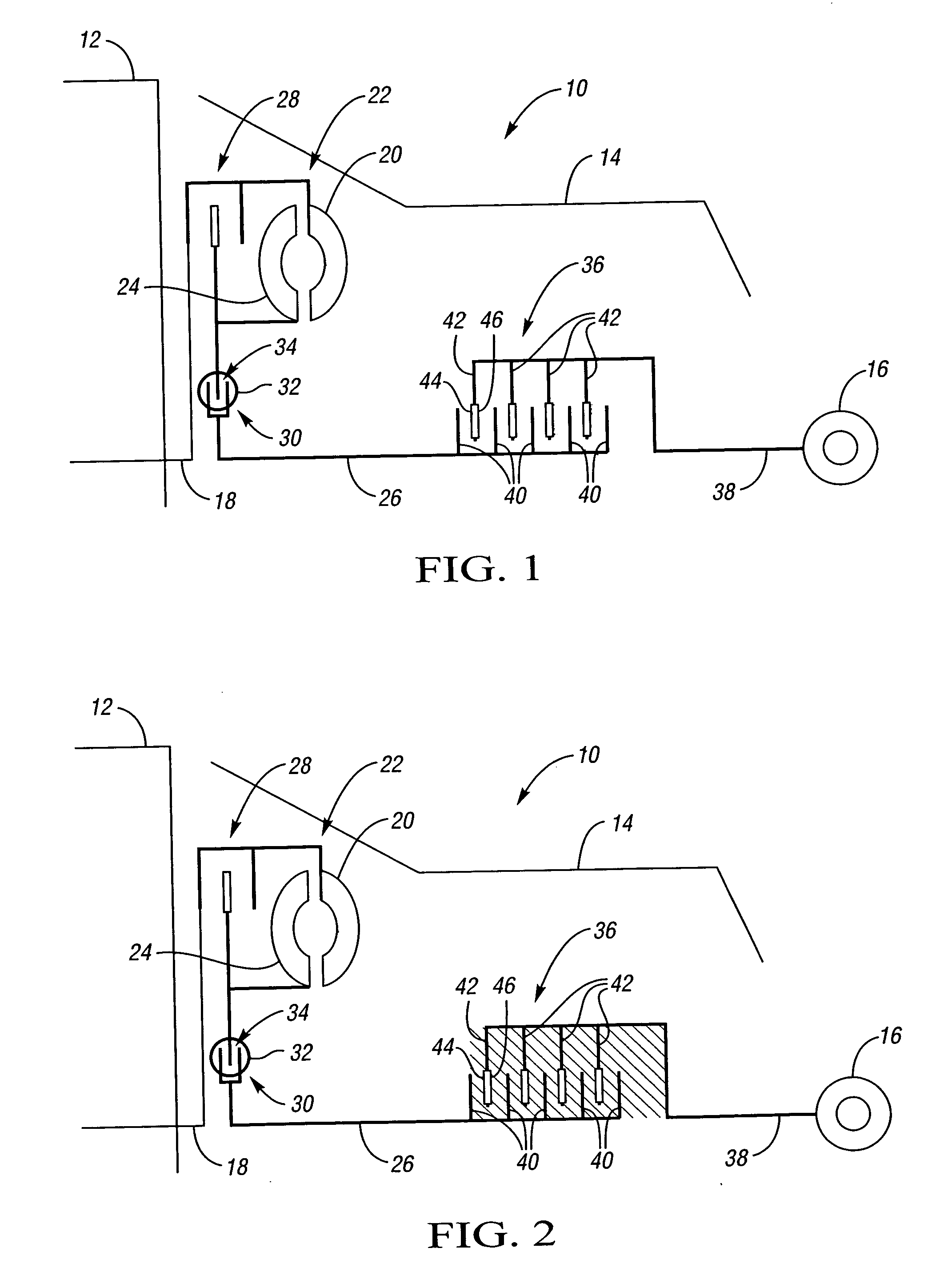
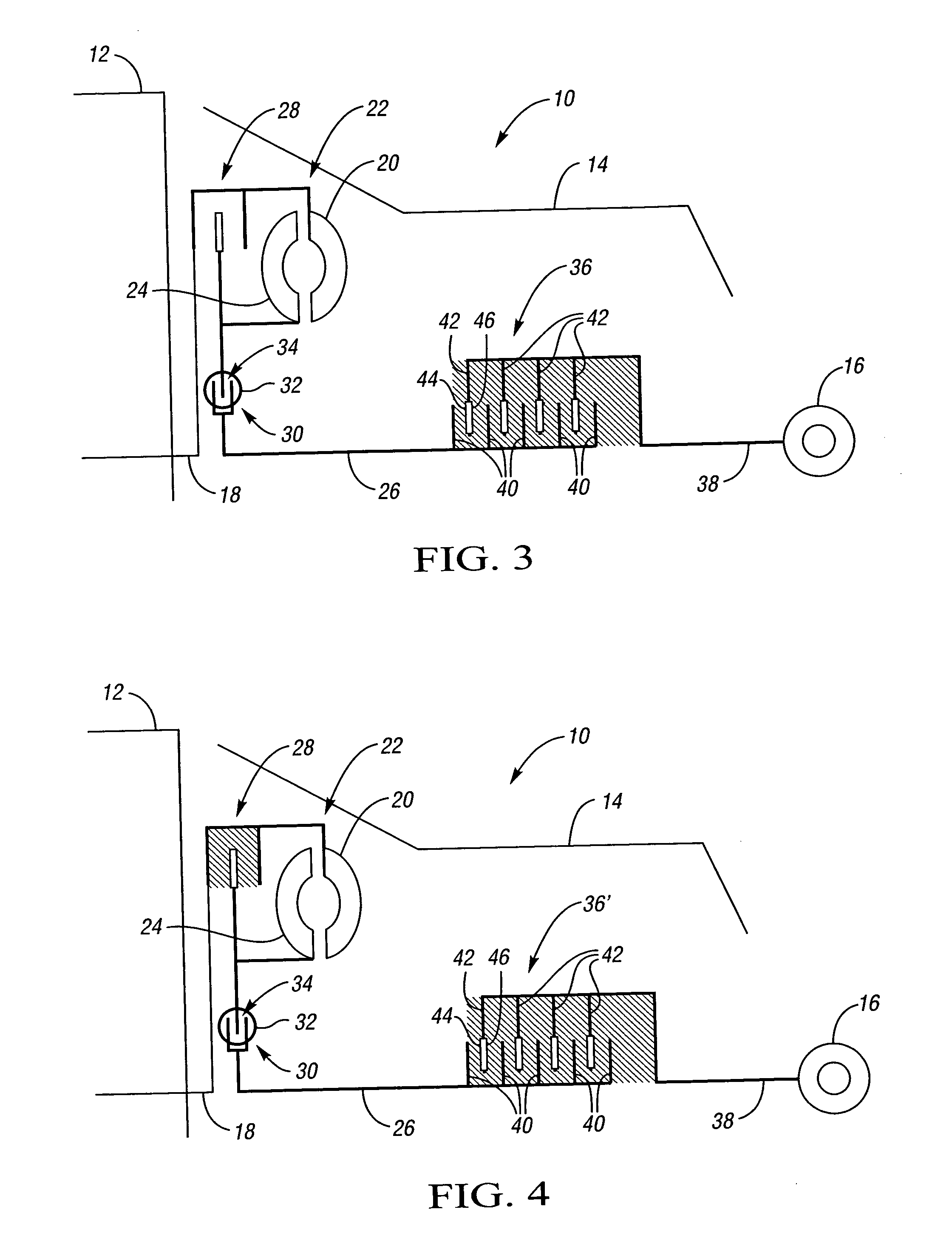
[0021] Referring to the drawings, wherein like characters represent the same or corresponding parts throughout the several views, there is seen in FIGS. 1 through 4 a powertrain 10. The powertrain 10 has a power source, such as a conventional internal combustion engine 12, a multi-speed automatic shifting power transmission 14, and a conventional final drive mechanism 16.

[0022] The engine 12 has an output shaft 18 with a pump section 20 of a hydrodynamic fluid drive device 22 rigidly mounted thereto. A turbine section 24 of the hydrodynamic fluid drive device 22 is mounted with respect to an input shaft 26 of the transmission 14. The hydrodynamic fluid drive device 22 may be either a fluid coupling or a torque converter, the operation of which are well known to those skilled in the art. Additionally, the present invention may include a lock-up clutch 28 in parallel with the hydrodynamic fluid drive device 22. The lock-up clutch 28 is operable to lock the input shaft 26 of the trans...


PUM


Abstract

The present invention provides a mechanism and method of launching a vehicle using a conventional automatic shifting power transmission. By slipping a first gear reaction clutch during a launch, an efficient hydrodynamic fluid drive with a low stall speed may be used with negligible impact on launch performance. The reduced stall speed characteristic of the hydrodynamic drive may provide improved efficiency in other vehicle operating regions.

Description

TECHNICAL FIELD [0001] The present invention relates to a mechanism and method of controlling an automatic shifting power transmission. BACKGROUND OF THE INVENTION [0002] In automatic shifting power transmissions, gear ratio changes are effected by selectively connecting members of planetary gear sets. This is accomplished by selectively engaging torque-transmitting devices such as brakes or clutches. For each gear ratio change, there is a corresponding sequence of off-going clutch disengagement and on-coming clutch engagement. By providing a regulated fluid pressure gain to the clutches, the smooth engagement and disengagement of the clutches may be accomplished. [0003] Additionally, a majority of automatic shifting power transmissions employ a hydrodynamic fluid drive, such as a torque converter or a fluid coupling, between the power source (engine) and a multi-speed gear configuration, such as the planetary gear arrangement discussed above. This hydrodynamic fluid drive will allo...

Claims


Application Information

Patent Timeline
25 Jan 2007
Publication
US20070021266A1
IPC
B60W10/00
CPC
F16D2500/10487; F16D2500/50224; F16D2500/5043; F16D2500/5048; Y10T477/6937; F16H61/00; F16H2312/02; Y10T477/6425
Inventors
ROSES, VICTOR M.