Acoustic flow straightener for turbojet engine fan casing

a turbojet engine and fan casing technology, which is applied in the direction of machines/engines, stators, liquid fuel engines, etc., can solve the problems of noise generation, achieve the effect of reducing fan noise, improving fan noise reduction, and maintaining aerodynamic performance and mechanical integrity

Active Publication Date: 2010-02-16
SN DETUDE & DE CONSTR DE MOTEURS DAVIATION S N E C M A
View PDF14 Cites 7 Cited by
  • Summary
  • Abstract
  • Description
  • Claims
  • Application Information

AI Technical Summary

Benefits of technology

[0004]The applicant company has set itself the objective of improving the reduction in the noise emitted by the fan in the context of this last configuration. The applicant company has, in particular, set itself the objective of developing a device capable of reducing fan noise while at the same time maintaining the aerodynamic performance and the mechanical integrity without increasing the mass.
[0006]By virtue of the invention, by acoustically treating at least some of the structural or nonstructural arms such as those that form part of the intermediate casing, it becomes possible to meet an objective of significant noise reduction.
[0007]Specifically, the solution of the invention allows a reduction in engine noise at the medium frequencies ranging from 2000 to 3000 Hz that has estimated significant acoustic performance between 0.5 EPNdB and 1 EPNdB within tolerance combined across the three measurement points used for acoustic certification. By being arranged radially in the flow channel this solution is able in particular to “trap” some of the acoustic energy which cannot be dissipated by parietal acoustic treatments.
[0008]The solution of the invention also has the advantage that it has a negligible impact on the aerodynamic performance of the fan provided that certain precautions are taken when implementing it. Thus, in order to limit friction losses, the perforations will be located on the intrados of the arms, which is where the flow velocities are lower, while at the same time minimizing the orifice diameters thereof such that d<1 mm. It is also very important to prevent any recirculation of air inside the arms which means that the perforated regions need to be positioned to take account of the static pressure profiles over the height of the arms.
[0009]The solution of the invention has the further advantage of carrying a very low weight penalty. The mass is similar to that of a casing with untreated hollow arms.
[0010]The solution of the invention has the further advantage of maintaining the conventional mechanical architecture of the component. This differs only slightly from a hollowed-out but not acoustically treated production arm. This feature also means that the manufacturing and industrialization costs are such that mass production can be envisioned.

Problems solved by technology

It is at this cascade that noise is generated as a result of the impact of fluctuations in speed and in pressure on the vanes and which are caused by the unsteady flow.

Method used


Image

  • Acoustic flow straightener for turbojet engine fan casing
  • Acoustic flow straightener for turbojet engine fan casing

Examples


Embodiment Construction

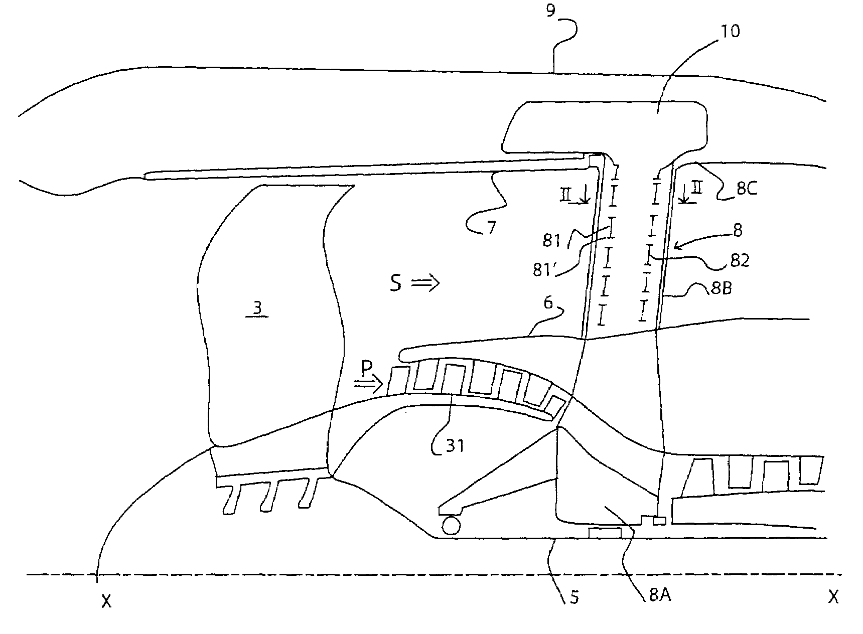
[0020]A bypass turbofan engine 1 with the fan located at the front comprises a fan rotor 3 mounted at the front end of a shaft 5 which is connected at the downstream end to a turbine, not depicted in the figure. The fan sucks in air and compresses it into an annular double stream, namely a primary flow P closest to the axis XX of the engine and a secondary flow S concentric therewith. The primary flow P passes through successive compression stages only the first 31 and 32 of which can be seen in FIG. 1. The primary flow P is thus compressed and guided as far as the combustion chamber. The gases resulting from combustion are directed toward the turbine rotors where the energy is recovered. The low-pressure turbine is connected to the rotor of the fan 3 by the LP shaft 5 the upstream end of which can be seen in the figure. The secondary flow S is guided downstream between the fairing 6 of the body of the primary flow and the external fan casing 7 and passes through the impeller formed...


PUM


Abstract

The present invention relates to a structural or non-structural turbojet engine fan casing connecting arm that also acts as a flow straightener downstream of the fan rotor. Its distinctive feature is that it is constructed to form an acoustic attenuator. In particular, it comprises a closed cavity and perforations on one of the faces so as to form a Helmholtz resonator. The arm forms part of the intermediate casing.

Description

BACKGROUND OF THE INVENTION AND DESCRIPTION OF THE PRIOR ART[0001]The present invention relates to the field of bypass turbojet engines and is aimed at attenuating the noise emitted by the engine, particularly the noise emitted by the fan.[0002]A bypass turbojet engine for transport airplane propulsion comprises a fan, generally on the upstream side, delivering an annular airflow with a primary central annular part which supplies air to the engine that drives the fan and a secondary external annular part which is ejected to the atmosphere thereby providing a significant proportion of the thrust. The fan is contained inside a casing which delimits the secondary or bypass flow. A structural element of the engine known as the intermediate casing comprises a hub supporting the shafts that connect the various rotors, an outer annular casing and radial connecting arms connecting these casings together. The radial arms transmit some of the forces between the engine and its support. At the ...

Claims


Application Information

Patent Timeline
Patent Type & Authority Patents(United States)
IPC IPC(8): F02K3/02
CPCF01D5/147F01D5/16F01D9/065F02K3/06F05D2260/96Y02T50/672Y02T50/673Y02T50/60
Inventor JULLIARD, JACQUES MICHEL ALBERTMOLINARI, OLIVIER MICHAELMOREL, PATRICK CHARLES GEORGESRIOU, GEORGES JEAN XAVIER
Owner SN DETUDE & DE CONSTR DE MOTEURS DAVIATION S N E C M A
Why Eureka
Try Eureka