Power control of a power amplifier

a power amplifier and power control technology, applied in the direction of rf amplifiers, automatic tone/bandwidth control, gain control, etc., can solve the problems of reducing the efficiency of the power amplifier, so as to prevent the saturation of each amplifier stage, improve efficiency, and limit distortion

Active Publication Date: 2006-01-12
SONY EUROPE BV
View PDF7 Cites 40 Cited by
  • Summary
  • Abstract
  • Description
  • Claims
  • Application Information

AI Technical Summary

Benefits of technology

[0027] In this case, the output of the final amplifier stage is of course the output of the power amplifier. By controlling the output power of each amplifier stage in this manner, it is possible to prevent each amplifier stage from saturating. This achieves the advantage of limiting the distortion which would otherwise occur when the output of an amplifier stage saturates and is therefore clipped.
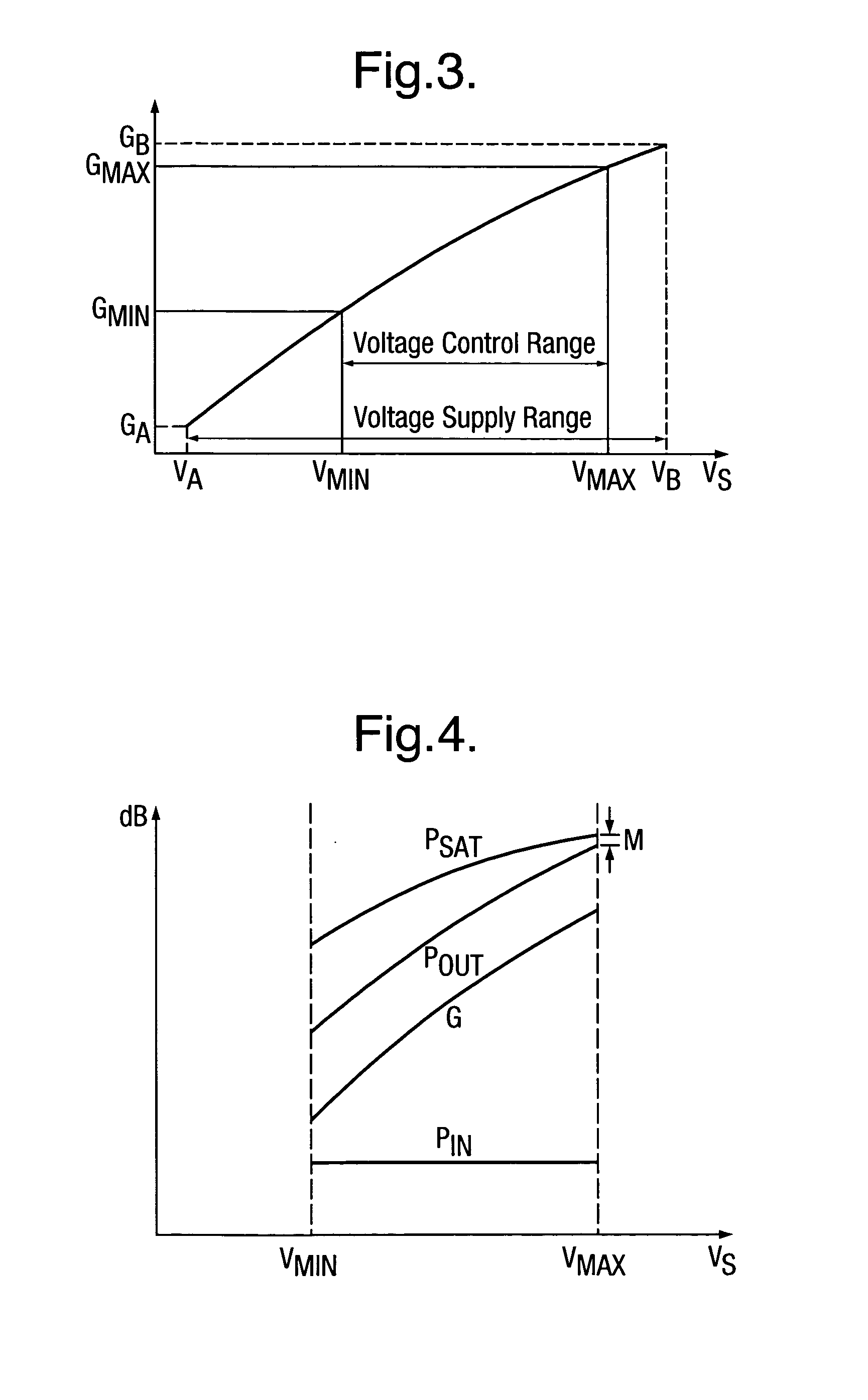
[0028] A preferred feature is that, across the voltage control range of the supply voltage, the gain of the power amplifier in decibels reduces at rate which is no more than the rate at which the saturation output power of the power amplifier in decibels reduces.
[0029] This provides the advantage of improving the efficiency. This may be understood by considering the fact that the actual output power is maintained below the saturation output power across the entire control range of the supply voltage. In general, such back-off of the power amplifier reduces efficiency. However, with thi

Problems solved by technology

As a result, it is normally only considered valid for constant envelope modulation schemes because they are insensitive to the gross AM non-linearities associated with the power control technique.
This is because the clipping of the radio frequency output voltage caused by operation of the power amplifier in the saturated region results in AM-AM and AM-PM distortion which is unacceptable in the context of variable envelope modulation (AM: amplitude modulation; PM: phase modulation).
Unfortunately, such backing-off of the input power into the linear region comes at the price of lower efficiency.
In addition, the variable gain amplifier consumes a significant current, typically 20 t

Method used


Image

  • Power control of a power amplifier
  • Power control of a power amplifier
  • Power control of a power amplifier

Examples


Embodiment Construction

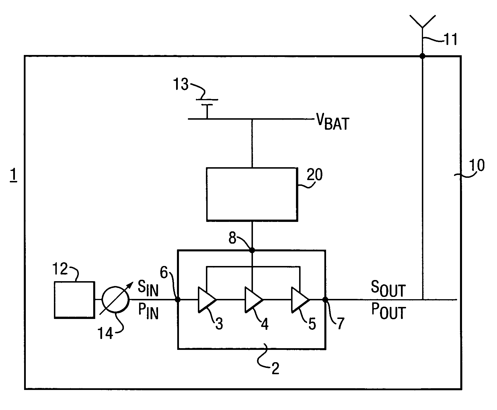
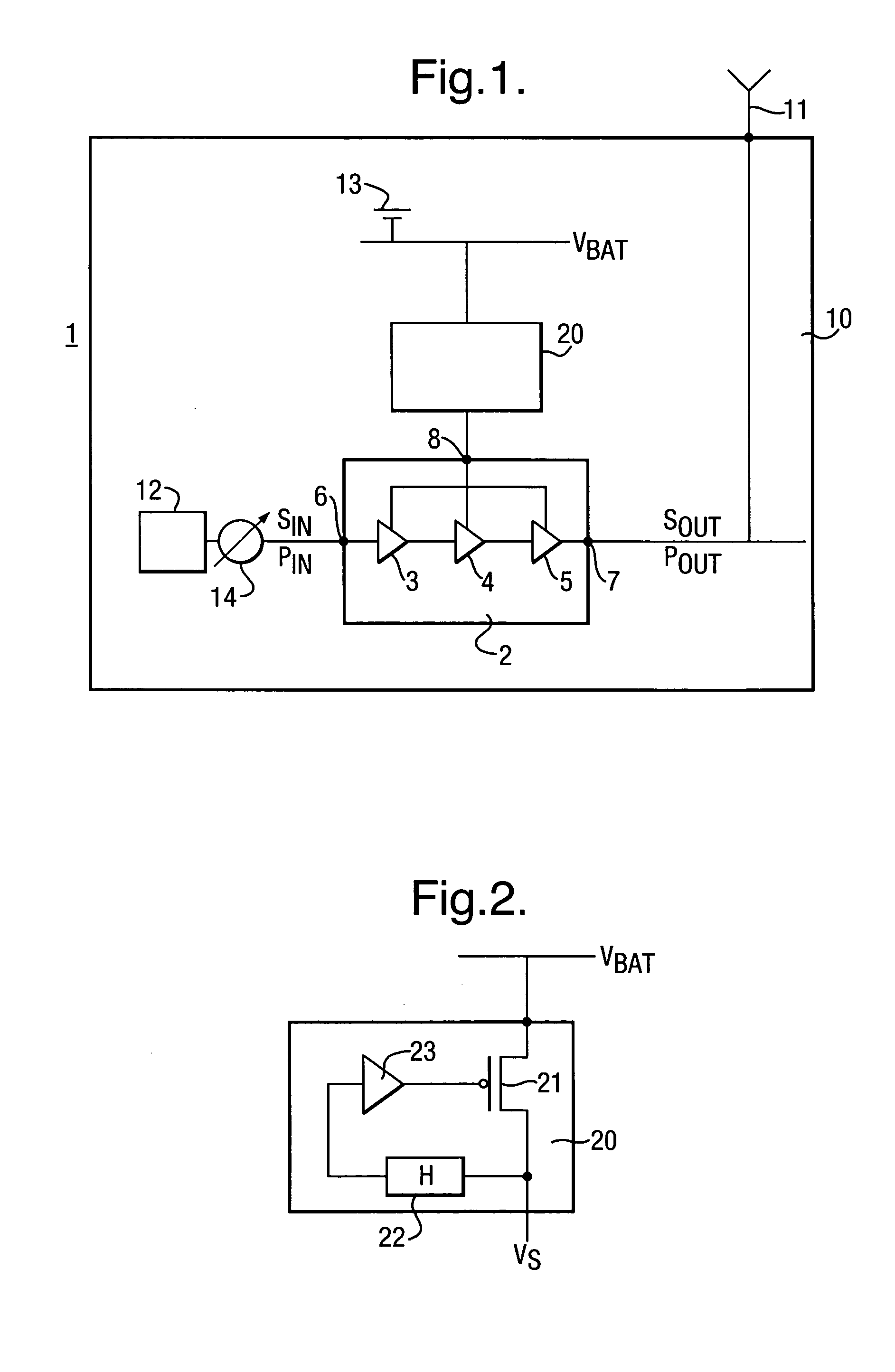
[0043] A power amplifier power control circuit 1 which embodies the present invention is shown in FIG. 1. The power amplifier power control circuit 1 has a power amplifier 2 which comprises three amplifier stages 3, 4 and 5 connected in series. An input signal SIN having an input power PIN is supplied to the input 6 of the power amplifier 2. The input signal SIN is amplified successively by the amplifier stages 3, 4 and 5 to produce an output signal SOUT at the output 7 of the power amplifier 2 having an output power POUT.

[0044] The power amplifier power control circuit 1 is provided inside a mobile terminal 10 for use with a wireless communication network. The output signal SOUT is supplied to an antenna 11 of the mobile terminal 10 for transmission. The input signal SIN is generated by the signal processing circuit 12 of the mobile terminal 10 and is modulated in accordance with the variable envelope modulation scheme of the specification of the wireless communication network in ...


PUM


Abstract

To effect power control of a power amplifier 2 having three amplifier stages 3, 4 and 5 used to amplify input signals modulated in accordance with a variable envelope modulation scheme, there is used a power amplifier 2 having a gain which reduces as the supply voltage to the power amplifier 2 reduces, and the output power POUT of the power amplifier 2 is controlled by regulation of the supply voltage VS. Taking advantage of the reduction in gain of the power amplifier 2, it is ensured that, in respect of each respective amplifier stage 3, 4 and 5 and at each respective value of the supply voltage in the voltage control range, the output power POUT of the respective amplifier stage 3, 4 and 5 is less than the saturation output power PSAT of the respective amplifier stage 3, 4 and 5. As a result, distortion of the signal is reduced. The power control technique improves efficiency over known techniques of backing off the output power and using a variable gain amplifier stage to control the output power.

Description

FIELD OF THE INVENTION [0001] The present invention relates to power control of a power amplifier used to amplify a signal modulated in accordance with a variable envelope modulation scheme. The present invention has particular application to power amplifiers used in wireless communication networks, for example in accordance with the EDGE specification or the WCDMA specification. DESCRIPTION OF RELATED ART [0002] In wireless communication networks it is necessary to control the power of signals output by the mobile terminals, in particular to minimise inter-channel interference and to conserve power. Such power control may be done by control of the power amplifier used to amplify the modulated signals. [0003] Many early wireless communication networks and in particular the first European digital cellular wireless networks used constant envelope modulation schemes, for example GMSK modulation as used in the GSM specification. The power control techniques used with such constant envel...

Claims


Application Information

Patent Timeline
IPC IPC(8): H03G3/10
CPCH03F1/0211H03F3/24H03F2200/504H03F2200/451H03F2200/408
Inventor CLIFTON, JOHN CHRISTOPHERDENNY, SIMONEATON, ANTHONY
Owner SONY EUROPE BV
Why Eureka
Try Eureka