
Signal processing method and apparatus

Active Publication Date: 2007-03-29
NEC CORP
View PDF5 Cites 23 Cited by
  • Summary
  • Abstract
  • Description
  • Claims
  • Application Information

AI Technical Summary

Benefits of technology

[0070] It is therefore an object of the present invention to provide a signal processing method that realizes noise cancellation in which the convergence time is short and distortion of output speech is limited for input signals of a signal-to-noise ratio having a broad range at the speech input terminal or reference input terminal.
[0071] It is another object of the present invention to provide a signal processor that realizes noise cancellation having short convergence time and little distortion in output speech for input signals of signal-to-noise ratios having a broad range in a speech input terminal or reference input terminal. MEANS FOR SOLVING THE PROBLEM
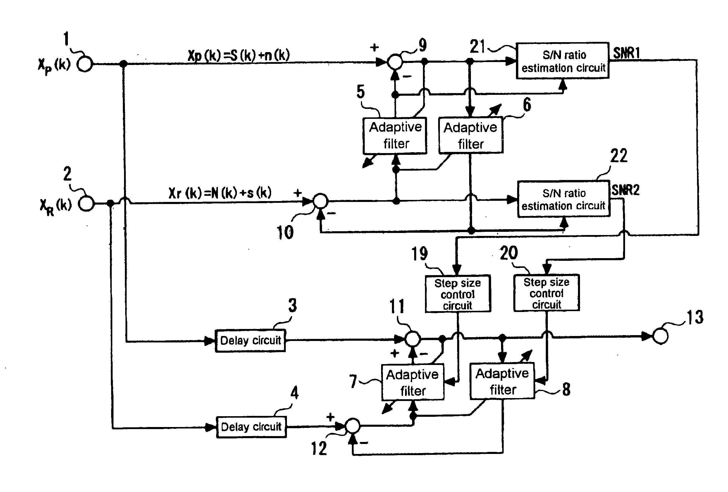
[0081] According to the present invention, by estimating signal-to-noise ratios, operating adaptive filters having step sizes which are appropriately controlled through the use of the estimated values of the signal-to-noise ratios, and using the signal-to-noise ratios estimated based on the output signal of the adaptive filters to determine the step sizes of other adaptive filters, signal processing having short convergence time, and moreover, having little distortion in output speech can be realized for an input signal having a signal-to-noise ratio that varies over a broad range at a speech input terminal or reference input terminal.

Problems solved by technology

Background noise signals mixed with these speech signals pose a serious problem when implementing speech encoding or speech recognition in a narrow-band speech encoder having a high degree of information compression, a speech recognition device, or the like.
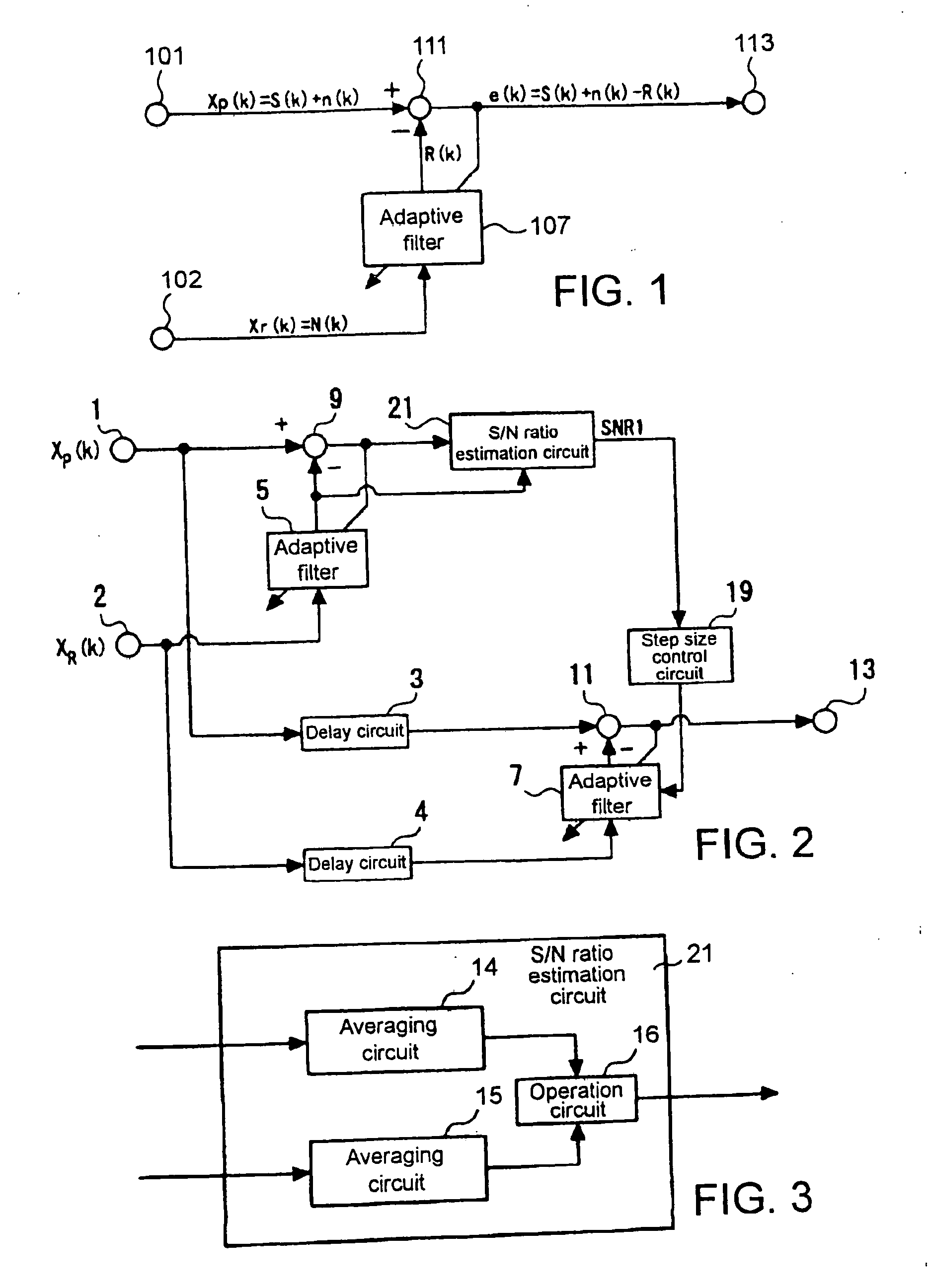
When step size α is large, the amount of correction of the coefficient increases and the convergence is therefore fast, but fluctuation of the coefficient also increases in the vicinity of the optimum value and the final residual error becomes great.
In contrast, when the step size α is small, the time required for convergence increases, but the final residual error becomes small.
However, as stated above decreasing the step size raises the problem of increase in the convergence time of adaptive filter 107.

Method used


Image

  • Signal processing method and apparatus
  • Signal processing method and apparatus
  • Signal processing method and apparatus

Examples


first embodiment

[0097] The signal processor of the present invention shown in FIG. 5 is provided with: speech input terminal 1; reference input terminal 2; output terminal 13; first delay circuit 3 for receiving first received sound signal XP(k) which is received from speech input terminal 1 and conferring to the first received sound signal a delay time that has been determined in advance to generate a first delayed received sound signal; second delay circuit 4 for receiving a second received sound signal XR(k) which is received from reference input terminal 2, giving the second received sound signal a delay time that is the same as that of first delay circuit 3 to generate a second delayed received sound signal; first subtractor 11 for subtracting a first pseudo noise signal from the first delayed received sound signal to generate a first error signal; a second subtractor 12 for subtracting the first pseudo speech signal from the second delayed received sound signal to generate a second error sign...

second embodiment

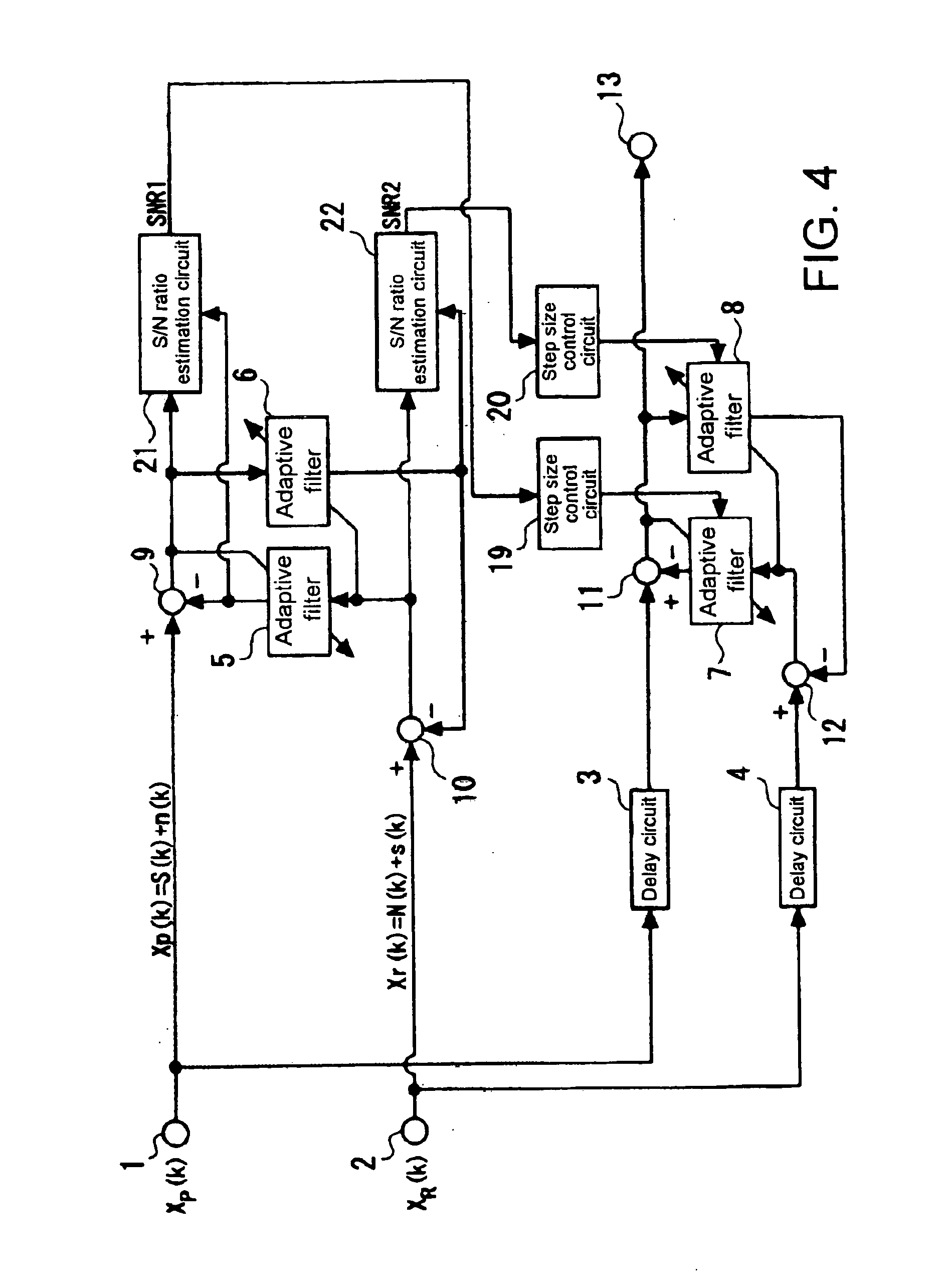
[0135] The signal processor of the second embodiment that is shown in FIG. 6 is provided with: speech input terminal 1; reference input terminal 2; output terminal 13; first delay circuit 3 for receiving first received sound signal XP(k) as input from speech input terminal 1 and giving a predetermined delay time to the first received sound signal to generate a first delayed received sound signal; second delay circuit 4 for receiving second received sound signal XR(k) as input from reference input terminal 2 and giving a delay time that is the same as that of first delay circuit 3 to second received sound signal to generate second delayed received sound signal; first subtractor 11 for subtracting a first pseudo noise signal from the first delayed received sound signal to generate a first error signal; second subtractor 12 for subtracting the first pseudo speech signal from the second delayed received sound signal to generate a second error signal; first adaptive filter 7 for receivin...

third embodiment

[0145] The signal processor of the third embodiment that is shown in FIG. 7 is provided with: speech input terminal 1; reference input terminal 2; output terminal 13; first delay circuit 3 for receiving first received sound signal XP(k) as input from speech input terminal 1 and giving a predetermined delay time to the first received sound signal to generate a first delayed received sound signal; second delay circuit 4 for receiving second received sound signal XR(k) which is received from reference input terminal 2 and giving the second received sound signal the same delay time as first delay circuit 3 to generate a second delayed received sound signal; first subtractor 11 for subtracting a first pseudo noise signal from the first delayed received sound signal to generate a first error signal; second subtractor 12 for subtracting the first pseudo speech signal from the second delayed received sound signal to generate a second error signal; first adaptive filter 7 for receiving the s...


PUM


Abstract

A signal processor includes: a first adaptive filter that takes a first signal as input and generates a first pseudo signal; a first subtractor that subtracts the first pseudo signal from a second signal to supply a first differential signal as output; a second adaptive filter that takes the first signal as input to generate a second pseudo signal; a second subtractor that subtracts the second pseudo signal from the second signal to supply a second differential signal as output; a first step size control circuit that generates a first step size used in updating the first adaptive filter in accordance with the relation between the second pseudo signal and the second differential signal; and a second step size control circuit that generates a second step size used in updating the second adaptive filter in accordance with the relation between the first signal and the second signal.

Description

TECHNICAL FIELD [0001] The present invention relates to a signal processing method and signal processing device, and more particularly to a method and device for eliminating other signals that are mixed with a desired signal that has been received from a microphone, handset, or communication path, or for accentuating a desired signal of this type. BACKGROUND ART [0002] Speech signals received from a device such as a microphone or handset are subjected to speech encoding or a speech recognition process. Background noise signals mixed with these speech signals pose a serious problem when implementing speech encoding or speech recognition in a narrow-band speech encoder having a high degree of information compression, a speech recognition device, or the like. Two-input noise cancellers employing adaptive filters are disclosed in References [1] to [9] and [23] as signal processors directed toward eliminating thus acoustically superposed noise components. [0003] A two-input noise cancell...

Claims


Application Information

Patent Timeline
IPC IPC(8): H04B15/00G06F17/10G10L21/0208G10L21/0224H03H21/00
CPCG10L21/0208H03H2021/0078H03H21/0012G10L2021/02165
Inventor SATO, MIKISUGIYAMA, AKIHIKO
Owner NEC CORP
Learn More