Vibrating motor and electronic device

a technology of vibrating motor and electronic device, which is applied in the direction of motor/generator/converter stopper, dynamo-electric converter control, mechanical vibration separation, etc., can solve the problem of difficult operation feel, and achieve the effect of preventing deterioration due to abrasion and the like, and prolonging the life of the vibrating motor

Inactive Publication Date: 2012-05-17
IC FAN V TECH
View PDF9 Cites 6 Cited by
  • Summary
  • Abstract
  • Description
  • Claims
  • Application Information

AI Technical Summary

Benefits of technology

[0030]According to the first to third aspects of the present invention, in the vibrating motor that is vibrated by rotationally driving the vibrator having an eccentric load, a driving current is applied to the vibrating motor, and an electric current in an opposite direction is subsequently applied to brake the rotation of the motor; therefore, the driving of the vibrator can be stopped against an inertial force when driving the vibrating motor, and thus the vibration can be instantly converged.
[0031]Since no friction occurs when stopping the driving of the vibrator, deterioration due to abrasion and the like can be prevented, and a lifespan of the vibrating motor can be lengthened.
[0032]Furthermore, the lifespan of the vibrating motor can also be lengthened as a result of the vibration convergence time being short, wasteful rotations due to an inertial force being prevented, and the number of rotations of the vibrator being reduced.
[0033]According to the fourth to seventh aspects of the present invention, in the vibrating motor with the vibrator that reciprocates by way of an action of a magnetic field, a driving current at predetermined frequency or in a predetermined phase is applied to drive the vibrator, and an electric current at different frequency or in a different phase is subsequently applied to the coil to suppress an inertia force of the vibrator and stop the driving; therefore, the vibration can be instantly converged.
[0035]Moreover, the lifespan of the vibrating motor can also be lengthened as a result of the fact that the vibration convergence time is short, thus wasteful rotations can be prevented, and the number of rotations of the vibrator can be reduced.

Problems solved by technology

On the other hand, in recent years, in portable electronic devices operated via a touch panel, a feel of operation is hard to obtain via such a touch panel; therefore, it is desired that a feel of operation can be imparted.

Method used


Image

  • Vibrating motor and electronic device
  • Vibrating motor and electronic device
  • Vibrating motor and electronic device

Examples


first embodiment

[0071]Next, descriptions are provided for operations and effects of the

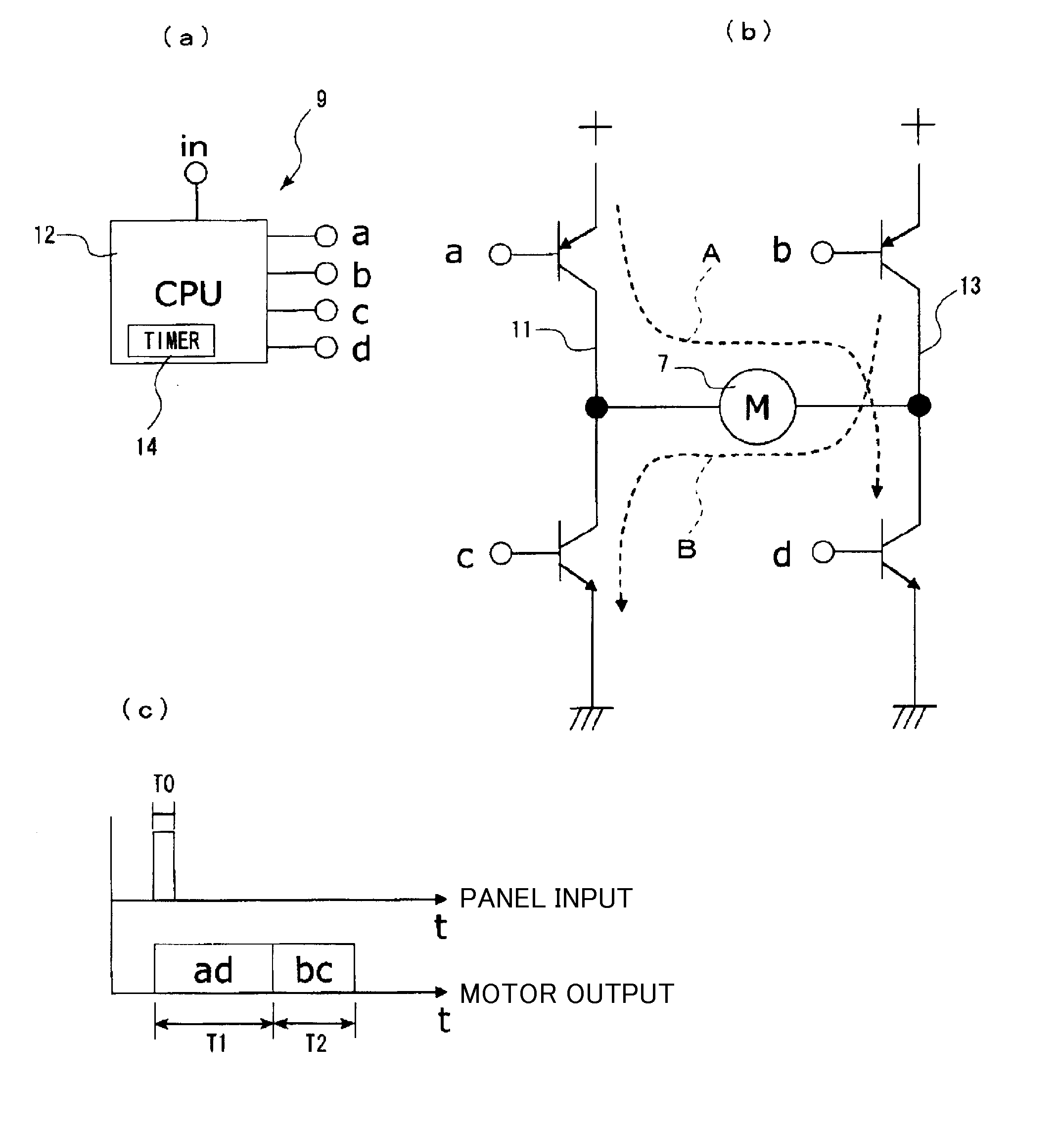
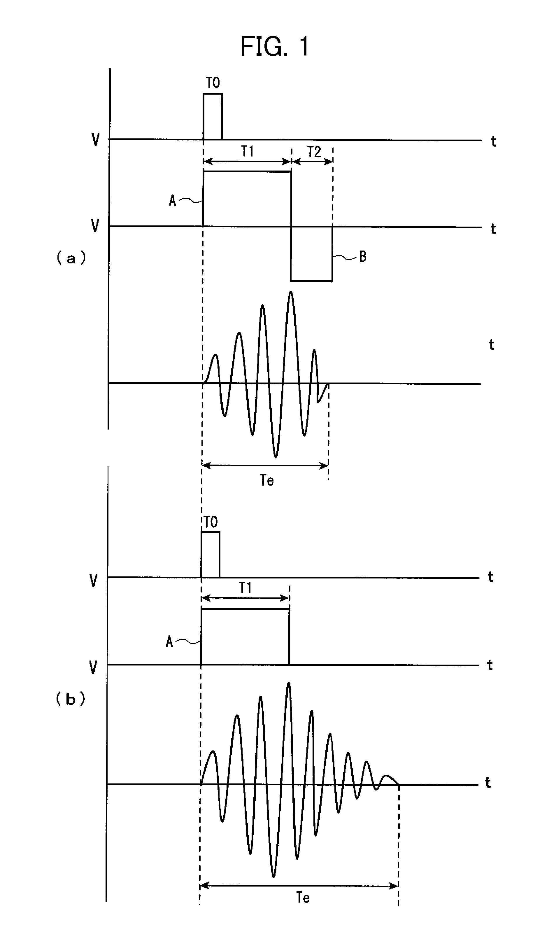
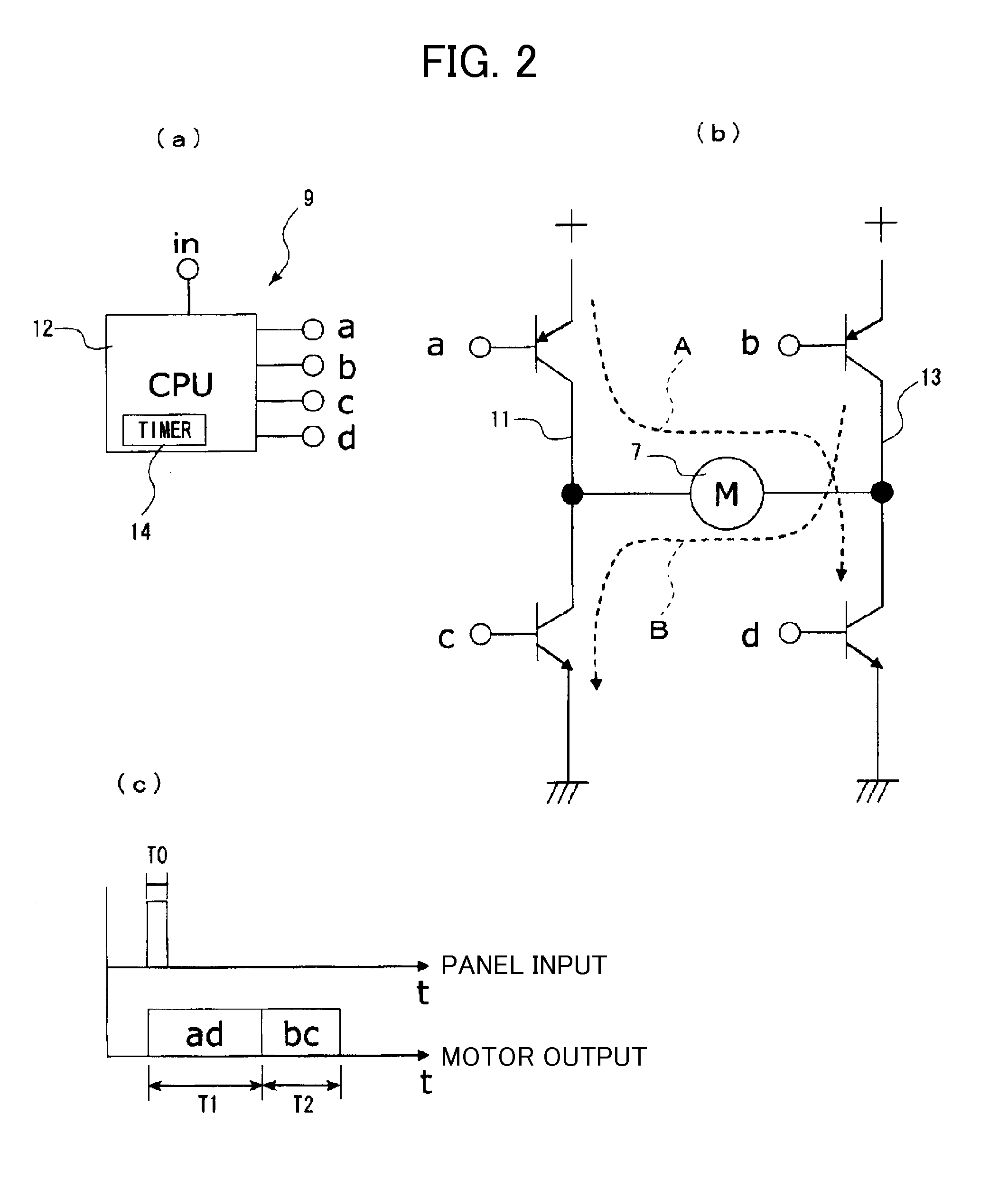
[0072]When an input is made from the operation unit 5, as shown in FIG. 1(a), the CPU 12 applies the driving pulse current A to the vibrating motor 7 to be driven for the period of time T1, and subsequently applies the braking pulse current B in the opposite direction for the period of time T2.

[0073]As a result of driving the vibrating motor 7, the rotational axis of the vibrating motor tends to keep rotating due to an inertial force, even after stopping applying the pulse current A thereto (see Te in FIG. 1(b)). However, in the present embodiment, as shown in FIG. 1(a), as a result of applying the braking pulse current B for the period of time T2 after applying the driving pulse current A for the period of time T1, the rotation of the vibrator 7c is braked, and the driving of the vibrating motor 7 is instantly stopped; therefore, it is possible to shorten rotation (vibration) convergence time Te of the vibrator ...

third embodiment

[0091]In other words, in the third embodiment, the magnet 23 is vibrated in synchronization with the cycle of the driving current, and as shown in FIG. 10, the driving current A as a sine wave (phase wave) in a predetermined cycle is supplied, the magnet 23 is vibrated in synchronization with the sine wave, and cosine wave (an electric current of which phase is shifted 90 degrees) is subsequently supplied as the braking current B shown with an alternate long and short dash line in the drawing. It should be noted that a broken line 28 in FIG. 10 illustrates movement (vibration) of the magnet 23.

[0092]According to the third embodiment, the magnet (vibrator) 23 reciprocates in synchronization with the driving current A to generate vibration, and as shown in FIG. 10, when the braking current B is applied, a magnetic field is generated in a direction opposite to the direction of moving the magnet 23 (for example, a direction of moving upward when the magnet 23 moves downward); therefore,...


PUM


Abstract

Provided are a vibrating motor with long life wherein vibration of the vibrating motor can be converged instantaneously, and an electronic device. Upon receiving an input signal from the operating section (5) of a touch panel, an electronic device (1) feeds a drive current (A) to a vibrating motor (7) and gives a sense of operation by vibrating the vibrating motor, wherein a brake current (B) is fed in the reverse direction after the vibrating motor (7) is driven by feeding the drive current (A) thereto and the vibrating motor (7) is damped thus converging vibration of the vibrating motor instantaneously.

Description

TECHNICAL FIELD[0001]The present invention relates to a vibrating motor, and to an electronic device including the vibrating motor.BACKGROUND ART[0002]Generally, a cylinder-type vibrating motor, in which a rotational axis with a weight (vibrator) fixed thereto is rotationally driven to generate vibration, and a coin-type vibrating motor, in which an eccentric armature (vibrator) is rotationally driven to generate vibration, are well known.[0003]Such a vibrating motor is installed in various electronic devices such as a cellular telephone device and a controller of a gaming machine; and for example, the cellular telephone device is vibrated by the vibrating motor upon receiving an incoming signal, and the controller is vibrated in accordance with functions of the gaming machine.[0004]On the other hand, in recent years, in portable electronic devices operated via a touch panel, a feel of operation is hard to obtain via such a touch panel; therefore, it is desired that a feel of operat...

Claims


Application Information

Patent Timeline
Patent Type & Authority Applications(United States)
IPC IPC(8): G06F3/041H02K33/16H02P3/10
CPCB06B1/161H02P25/027G06F3/016H02P25/032
Inventor MORI, KOJI
Owner IC FAN V TECH
Why Eureka
Try Eureka