
Soil remediation of mercury contamination

a technology for soil remediation and mercury contamination, applied in the direction of separation process, dispersed particle separation, chemistry apparatus and processes, etc., can solve the problems of reducing electrical resistance, limiting the effectiveness of radar as mercury locating test, and testing may not give accurate concentration and depth information of contamination

Inactive Publication Date: 2005-11-08
BOARD OF RGT THE UNIV OF TEXAS SYST
View PDF66 Cites 38 Cited by
  • Summary
  • Abstract
  • Description
  • Claims
  • Application Information

AI Technical Summary

Benefits of technology

[0025]Location, extent, and concentration of mercury contamination may be determined prior to installing a soil remediation system that will remove or reduce to acceptable levels contaminants within the soil. Non-intrusive tests may be used to establish the location of mercury within the soil. The use of radar, gravimetric surveys, and / or electromagnetic surveys may determine the presence of mercury within the soil. The metallic characteristics of mercury may make large quantities of mercury within the soil detectable using radar. The presence of water within the soil may limit the effectiveness of radar as a mercury locating test. The presence of mercury within soil may increase the average density of the soil. A measurable increase in gravity may be indicated above soil that is contaminated with mercury. A gravity survey may be used to detect density anomalies in the soil. A detected anomaly may indicate the presence of mercury, or the detected anomaly may indicate the presence of some other type of density anomaly in the soil. In addition to increasing the average density of the soil, mercury may decrease the electrical resistance of the soil and cause induced polarization. Radar indications, density anomalies, decrease in soil resistance, and / or the presence of induced polarization may indicate the presence of mercury contamination within an area of soil.
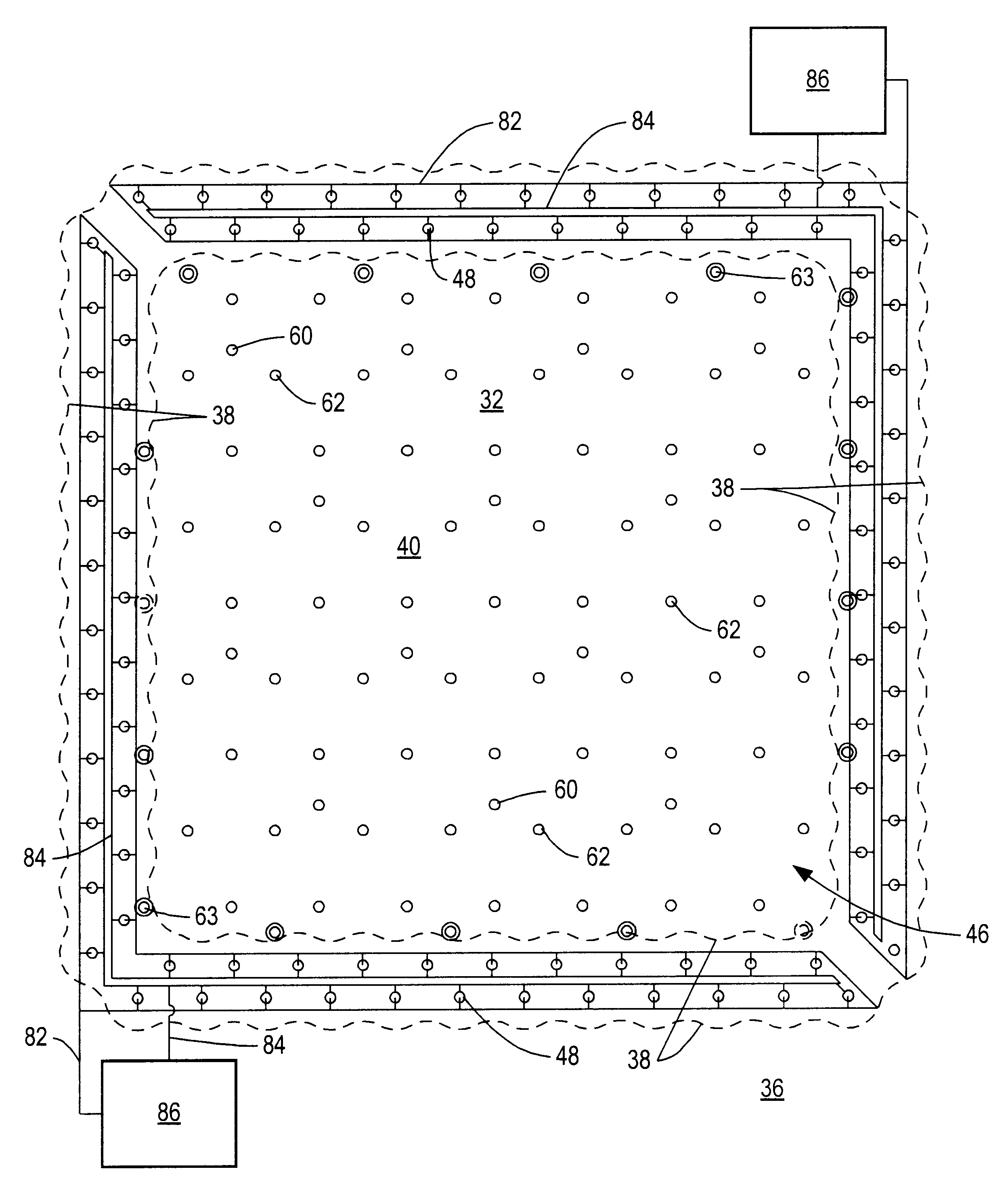
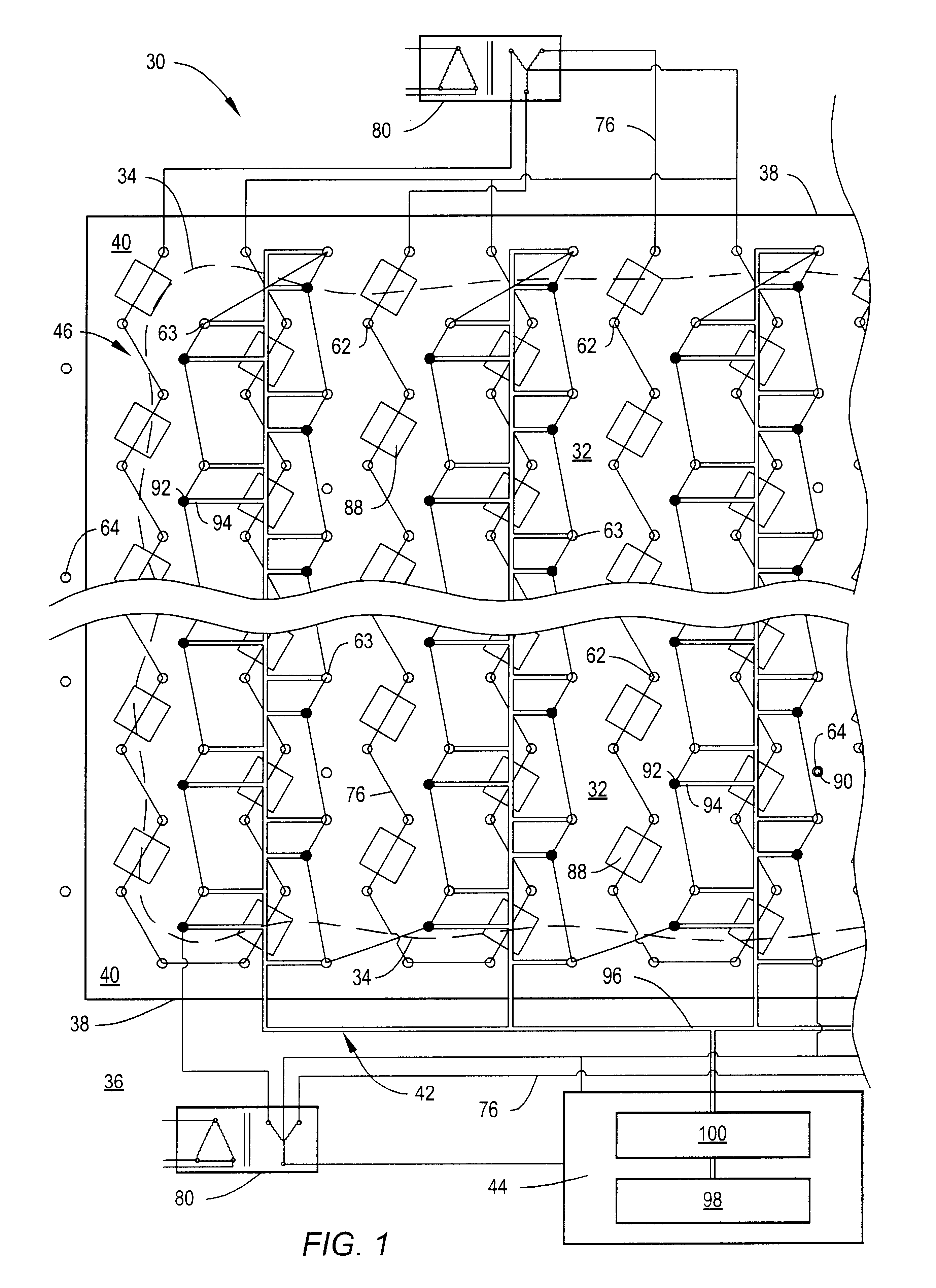
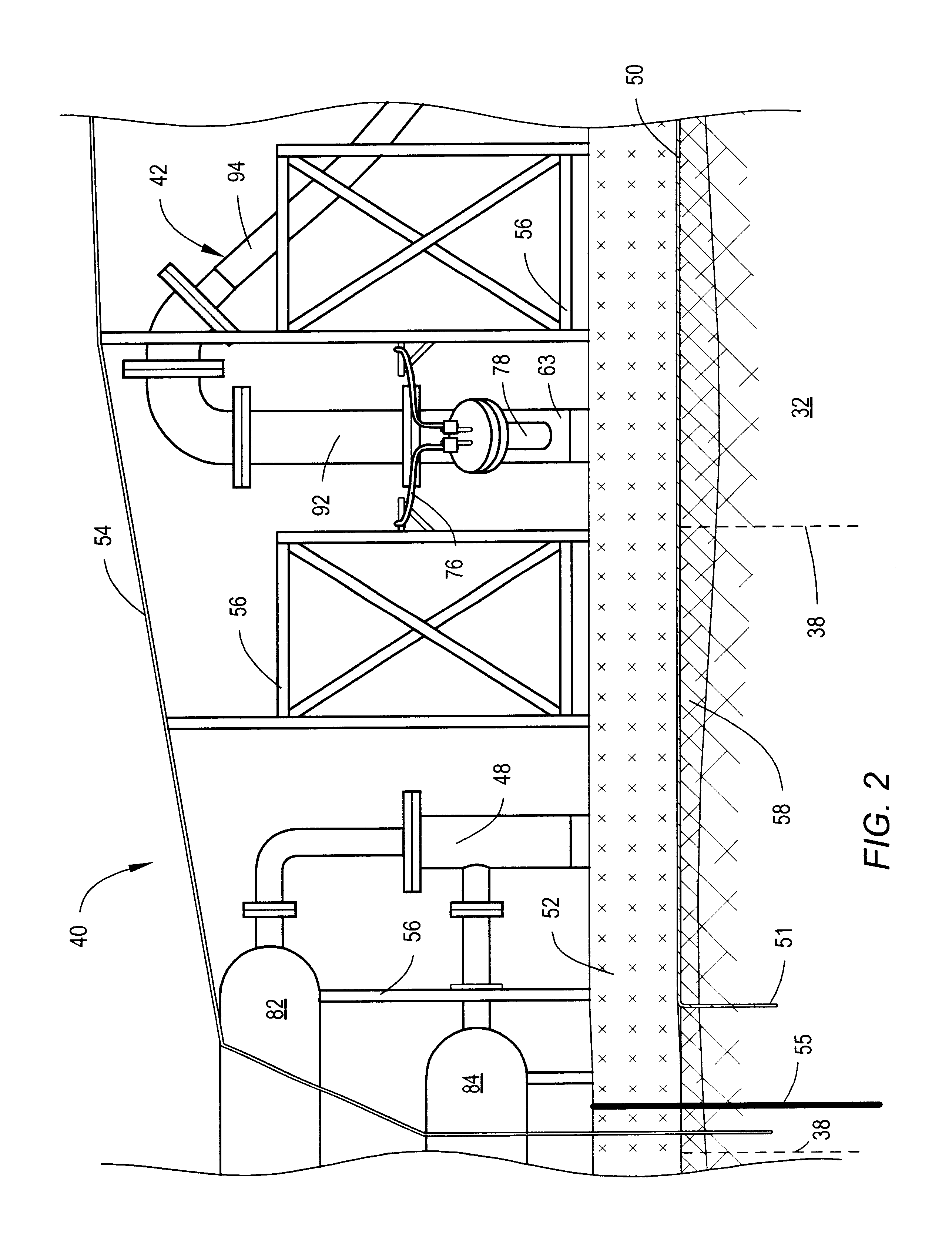
[0027]A soil remediation system used to treat mercury contaminated soil may be an ISTD soil remediation system. Heat may be applied to the soil by thermal blankets and / or heater wells. The type of soil heater may be determined based on the depth of the contaminants within the soil. Heater blankets may be used when contamination is close to the ground surface. Heater wells may be used when the contamination is deeper in the soil. The heat applied to the soil may raise the soil temperature above the boiling point of mercury throughout a treatment area. A ring or rings of heater-extraction wells may surround other remediation wells in a treatment area. The heater-extraction wells may inhibit migration of contamination from the treatment area during soil remediation.
[0028]Containment of mercury within the treatment area and reduction of airflow throughout the treatment area may be enhanced by a ground cover and by a barrier around a periphery of the treatment area. The barrier may inhibit migration of soil contamination into adjacent areas. The barrier may also inhibit fluid flow into the treatment area from adjacent areas. The barrier may be formed of sections of steel plate or other type of material that are driven into the soil around the periphery of the treatment area. Grouting, high temperature rubber seals, or other types of seals may be used to couple individual sections together. Alternatively, the barrier may be a frozen barrier formed by freeze wells placed around the periphery of the treatment area.
[0029]A ground cover for a soil remediation system may inhibit release of vapor into the air from a treatment area. The ground cover may also inhibit fluid from being drawn into the soil from the ground surface. In an embodiment, the ground cover may include a first steel sheet placed on the surface of the ground, a layer of insulation on top of the first steel sheet, and a vapor barrier over the insulation. Portions of wells extending into the soil may pass through the first steel sheet. The wells may be welded or otherwise sealed to the barrier. The vapor barrier may inhibit release of material that escapes past the first steel sheet and may also inhibit air and / or water from being drawn into the soil from the surface. The vapor barrier may be a steel barrier and / or a polymer barrier. The polymer barrier may be, but is not limited to, polyethylene, polypropylene, silicone rubber, or combinations thereof. The vapor barrier may be sloped to direct runoff rainwater to a desired location. Condensate formed on an interior side of the vapor barrier may be gathered and introduced into a treatment system of the soil remediation system to ensure that any contaminants within the condensate are properly treated. A support structure may be placed on top of the first steel sheet. The support structure may support wells, risers, wiring, collection piping and other structures that pass into or out of the ground within the treatment area.
[0030]A soil remediation system may include a perimeter barrier that surrounds or partially surrounds a treatment area. The perimeter barrier may be a freeze wall, a grout wall, and / or a number of sheets inserted into the ground to a desired depth and sealed together. A seal may be formed between a portion of a ground cover and the perimeter barrier. The seal may be, but is not limited to, a weld; adhesive; and / or gaskets and clamping force provided by clamps, screws, bolts, or other types of fasteners. The perimeter barrier may inhibit migration of contaminants out of the treatment area. The perimeter barrier may also inhibit entry of fluid into the treatment area from areas adjacent to the treatment area.

Problems solved by technology

The presence of water within the soil may limit the effectiveness of radar as a mercury locating test.
In addition to increasing the average density of the soil, mercury may decrease the electrical resistance of the soil and cause induced polarization.
Such tests may indicate an area of mercury contamination, but the tests may not give accurate concentration and depth information of the contamination.

Method used


Image

  • Soil remediation of mercury contamination
  • Soil remediation of mercury contamination
  • Soil remediation of mercury contamination

Examples


Embodiment Construction

[0040]An in situ thermal desorption (ISTD) process system may be used to remediate contaminated soil. An ISTD soil remediation process involves in situ heating of the soil to raise the temperature of the soil while simultaneously removing off-gas by vacuum. Heating the soil may result in removal of contaminants by a number of mechanisms. Such mechanisms may include, but are not limited to: vaporization and vapor transport of the contaminants from the soil; evaporation or entrainment and removal of contaminants in an air or water vapor stream; and / or thermal degradation or conversion of contaminants into non-contaminant compounds by pyrolysis, oxidation, or other chemical reactions within the soil (e.g., contaminants other than mercury such as hydrocarbon and / or chlorinated hydrocarbon contaminants).

[0041]An ISTD soil remediation process may offer significant advantages over soil vapor extraction (SVE) processes and processes that depend on the injection of drive fluids, chemical rea...


PUM


Abstract

An in situ soil remediation system may be used to remove or reduce levels of mercury contamination within soil. The soil remediation system may also remove or reduce levels of other contaminants within the soil. Mercury may be vaporized within the soil by a heating system. The vaporized mercury may be removed from the soil by a vacuum system. The vaporized mercury may pass through heated risers that elevate the vaporized mercury. After the vaporized mercury passes from the heated risers, the vaporized mercury may be allowed to cool, condense, and flow downward to a treatment facility. Removing mercury from the soil as a vapor may provide an economical, safe, and efficient way to remediate mercury contaminated soil.

Description

PRIORITY CLAIM[0001]This application claims priority to U.S. Provisional Application No. 60 / 336,325 entitled “Soil Remediation of Mercury Contamination,” filed Oct. 24, 2001. The above-referenced provisional application is hereby incorporated by reference as if fully set forth herein.BACKGROUND OF THE INVENTION[0002]1. Field of the Invention[0003]The present invention generally relates to treatment of contaminated soil. An embodiment of the invention relates to in situ thermal desorption soil remediation of mercury contaminated soil.[0004]2. Description of Related Art[0005]Contamination of soil has become a matter of concern in many locations. “Soil” refers to unconsolidated and consolidated material in the ground. Soil may include natural formation material such as dirt, sand, and rock, as well as other material, such as fill material. Soil may become contaminated with chemical, biological, and / or radioactive contaminants. Contamination of soil may occur in a variety of ways, such ...

Claims


Application Information

Patent Timeline
IPC IPC(8): B01D53/00B09C1/02B09C1/08B09C1/00B09C1/06B01D53/64B09B3/00
CPCB01D53/002B09C1/02B09C1/06B09C1/08B01D2257/602B09C2101/00
Inventor VINEGAR, HAROLD J.STEGEMEIER, GEORGE L.
Owner BOARD OF RGT THE UNIV OF TEXAS SYST
Learn More