Grooved anode for electrolysis cell

Inactive Publication Date: 2012-05-24
RIOTINTO ALCAN INT LTD
View PDF6 Cites 22 Cited by
  • Summary
  • Abstract
  • Description
  • Claims
  • Application Information

AI Technical Summary

Problems solved by technology

The accumulation of these gas bubbles causes:electrical variations and instabilities,a high frequency and long duration of anode effects,an increased possibility of the opposite reaction and therefore a loss of productivity because of the short distance between the layer of aluminum produced and the CO2 bubbles,an increased consumption of carbon and the formation of harmful gases because of the transformation of CO2 as it comes into contact with the carbon.
A well-known limit to the use of these grooves results from the fact that the depth of the grooves from the lower surface of the anode blocks is limited in order not to disturb the mechanical and physical intactness of the carbonaceous anode blocks.
The p

Method used


Image

  • Grooved anode for electrolysis cell
  • Grooved anode for electrolysis cell
  • Grooved anode for electrolysis cell

Examples


first embodiment

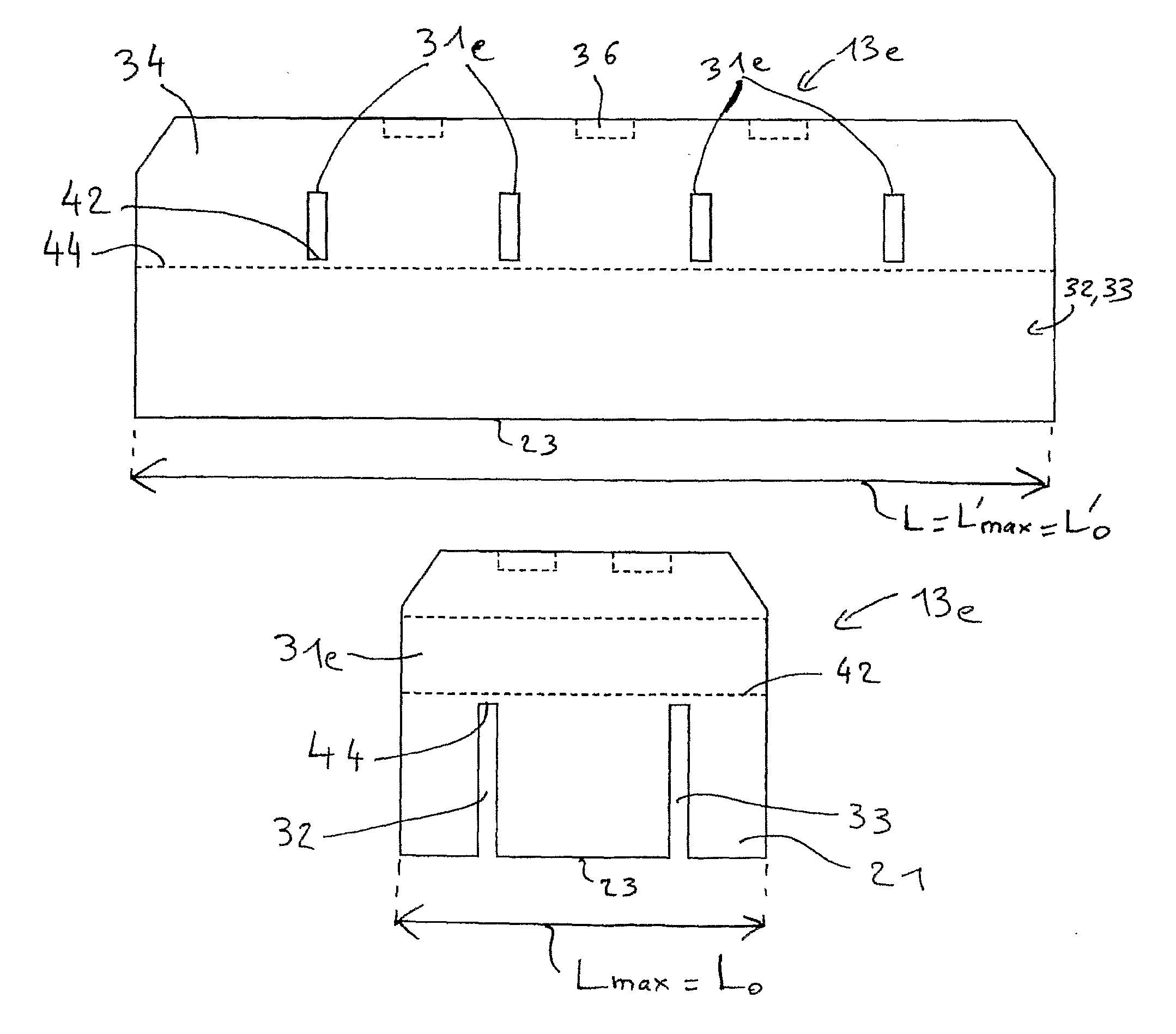
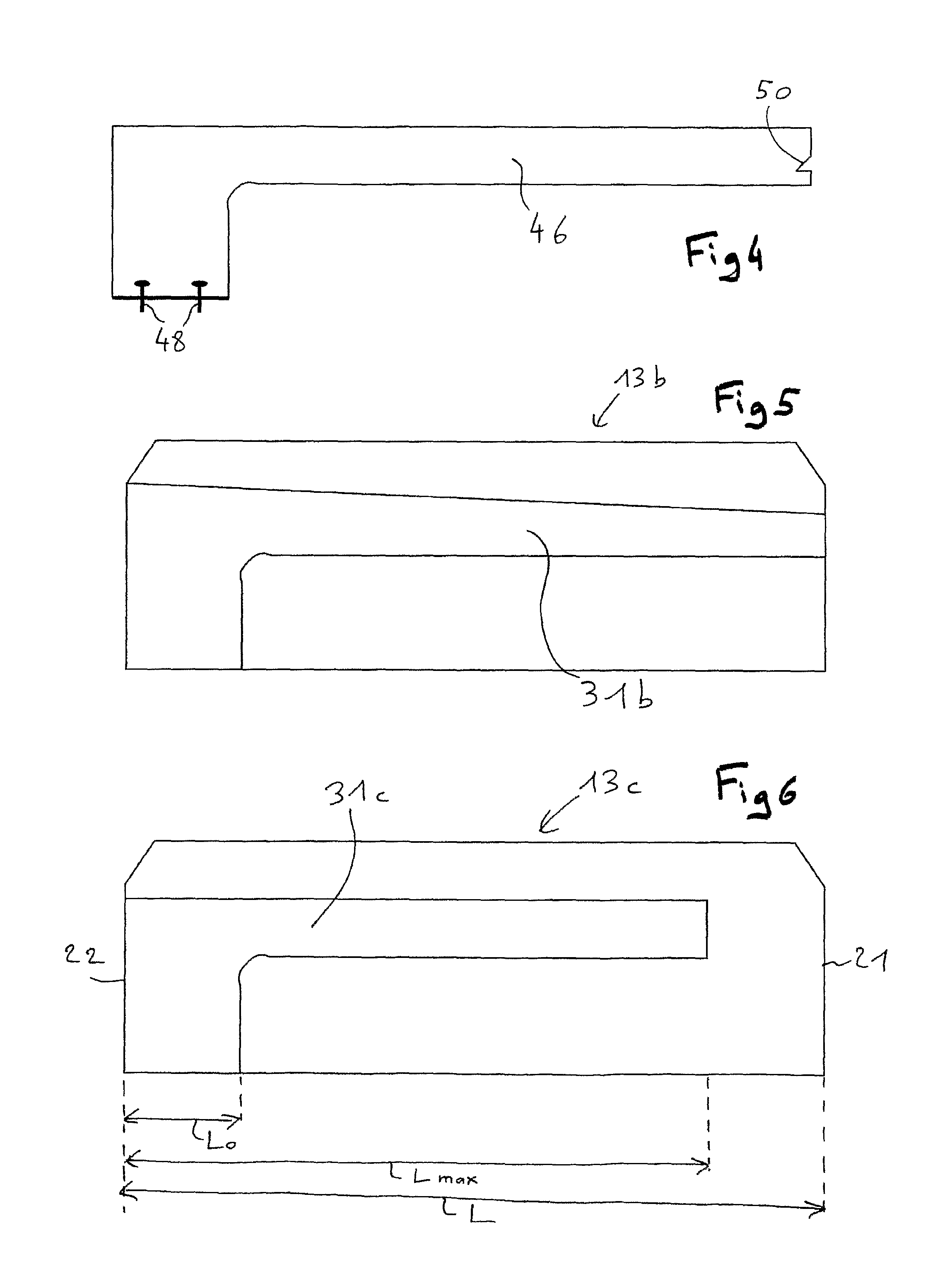
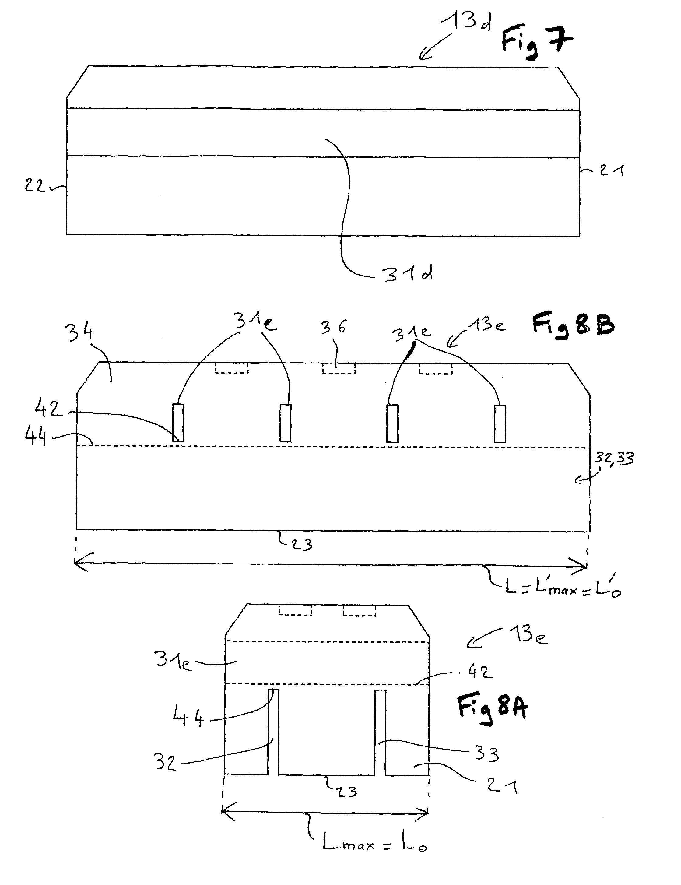
[0062]FIGS. 2A, 2B and 3 show an anode block 13a according to the invention. The anode block 13a is typically of right-angled parallelepipedic shape of length L between two opposite short side faces 21 and 22 typically vertical and of height H between a typically horizontal lower face 23 and a higher face 24. As shown in FIGS. 2A, 2B and 3, the higher edges can be cut away to limit carbon losses. The anode blocks are designed to be consumed down to a maximum wear height indicated by arrows 25.

[0063]The anode block 13a comprises a first groove 31a and two second grooves 32 and 33.

[0064]The second grooves 32, 33 typically pass right through the anode block in the direction of length L. FIGS. 2A and 2B, which shows the short opposite side faces 21, 22 of the anode block 13a, show that these second grooves 32, 33 lead onto the lower face 23 throughout its length and onto the two short side faces. Consequently, the second grooves 32, 33 lead onto the lower face 23 over lengths L′0 equal ...


PUM

PropertyMeasurementUnit
Fractionaaaaaaaaaa
Fractionaaaaaaaaaa
Timeaaaaaaaaaa

Abstract

The subject of the invention is an anode block (13, 13a-13e) made of carbon for a pre-baked anode (4) for use in a metal electrolysis cell (1) comprising a higher face (24), a lower face (23), designed to be laid out opposite a higher face of a cathode (9), and four side faces (21,22,34), and including at least one first groove (31a-31e) leading onto at least one of the side faces, in which the first groove has a maximum length Lmax in a plane parallel to the lower face, and characterized in that the first groove does not lead onto said lower or higher faces, or leads onto said lower or higher faces over a length L0 less than half the maximum length Lmax.

Description

SCOPE OF THE INVENTION [0001]The invention relates to the production of aluminum by igneous electrolysis using the Hall-Héroult process, and more particularly the pre-baked anodes used in aluminum production plants and comprising an anode block made of carbon, a manufacturing process for such anode blocks and a device designed for the manufacture of such anode blocks.BACKGROUND OF RELATED ART [0002]Metallic aluminum is produced industrially by igneous electrolysis, namely by electrolysis of alumina in solution in a molten cryolite bath, known as an electrolysis bath, using the well-known Hall-Héroult process. The electrolysis bath is contained in cells which comprise a steel container coated on the inside with refractory and / or insulating materials, and cathodic elements located at the bottom of the cell. Anode blocks made of carbonaceous material are partially immersed in the electrolysis bath. Each tank and the corresponding anodes form what is often called an electrolysis cell. T...

Claims


Application Information

Patent Timeline
IPC IPC(8): C25B11/12C25C1/22B28B1/08C25B9/00
CPCC25C7/025C25C3/125
Inventor BERLIN, GEOFFREYCAMIRE, JEANEMMETT, DARANFOSTER, YVANSERVANT, GUILLAUMEJONVILLE, CHRISTIANMANWARING, MALCOLM
Owner RIOTINTO ALCAN INT LTD
Why Eureka
Try Eureka