Method of generating energy in a power plant comprising a gas turbine, and power plant for carrying out the method

a gas turbine and power plant technology, applied in the direction of combustion-air/fuel-air treatment, lighting and heating apparatus, etc., can solve the problems of large and expensive devices for removing cosub>2 /sub>, low carbon-dioxide concentration in the exhaust gas, and carbon-dioxide partial pressur

Inactive Publication Date: 2005-02-10
ALSTOM TECH LTD
View PDF10 Cites 214 Cited by
  • Summary
  • Abstract
  • Description
  • Claims
  • Application Information

AI Technical Summary

Benefits of technology

[0035] It may also be advantageous if steam is generated by means of the hot flue gas issuing from the turbine, and the generated steam is partly injected into the combustor and is partly used in the CO2 separator, and if the compressed gas coming from the CO2 separator is subsequently compressed in a booster compressor, and the subsequently compressed gas, in a gas/gas heat exchanger, ex

Problems solved by technology

The main disadvantage of this boundary condition consists in the fact that the CO2 partial pressure is very low on account of the low CO2 concentration in the flue gas (typically 3-4% by volume) and therefore large and expensive devices for removing the CO2 are required.
If the predominant proportion of the carbon dioxide (80-95%) in the compressed working medium is removed, this results in low carbon-dioxide concentrations in the exhaust gas and consequently in the recirculation to the compressor and the carbon-dioxide separation unit.
In summary, it may be said that separation of most of the carbon dioxide downstream of the compressor in a high-pressure separation leads to carbon-dioxide partial pressures which are rather on the low side during the separation, a factor which works against the developmen

Method used


Image

  • Method of generating energy in a power plant comprising a gas turbine, and power plant for carrying out the method
  • Method of generating energy in a power plant comprising a gas turbine, and power plant for carrying out the method
  • Method of generating energy in a power plant comprising a gas turbine, and power plant for carrying out the method

Examples


Embodiment Construction

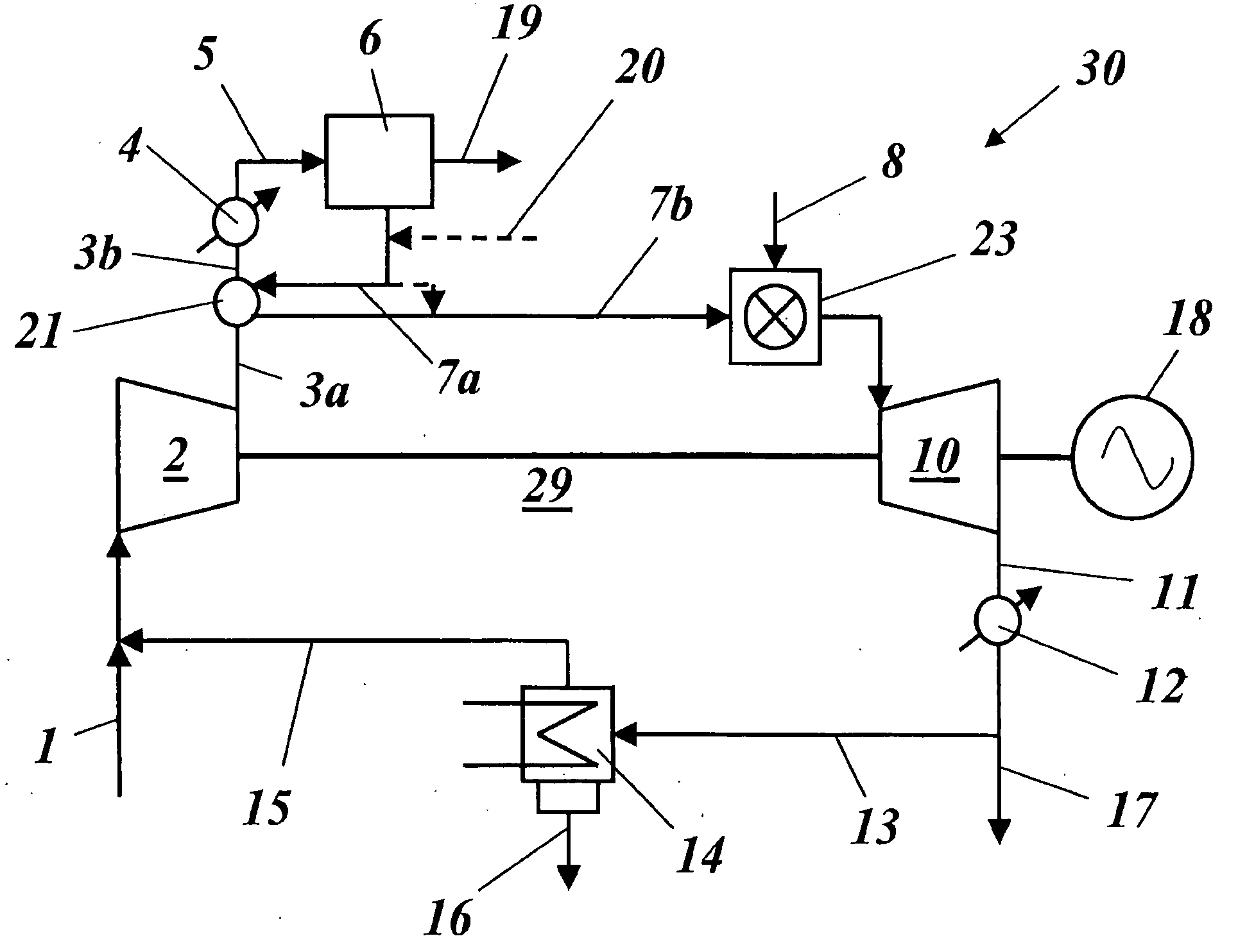
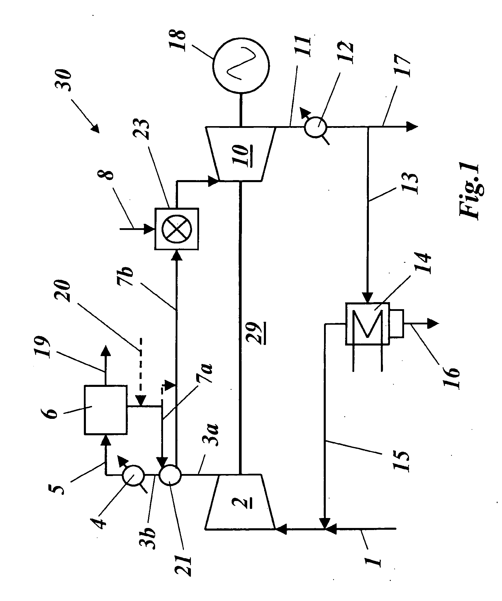
[0047] Described in the publication WO-A1-02 / 103176 mentioned at the beginning, as in the present FIG. 1, is a power plant 30 with a gas turbine 29, in which air or air 1 enriched with oxygen is mixed with recirculated flue gas 15 and is then passed into the compressor 2. The compressed gas 3a, 3b then flows to a heat exchanger 4, where it is cooled down to a temperature level (typically 30-60° C.) suitable for CO2 absorption. The relatively cool compressed gas 5 then enters a CO2 separator 6, where (and this is very important) 80-90% of the CO2 is separated. The compressed gas 7a, 7b at the outlet of the CO2 separator 6 is then passed to the combustor 23 and is burned there with a gaseous or liquid fuel 8, normally natural gas. The hot flue gas 9 is then expanded in a turbine (or an expander) 10, which in turn drives the compressor 2 and generates electrical energy by means of a generator 18. After the expansion in the turbine 10, the flue gas enters a heat-recovery steam generator...


PUM


Abstract

A method of generating energy in a power plant (30) having a gas turbine (29), includes a first step a gas containing air (1) is compressed in a first compressor (2) of the gas turbine (29), a second step the compressed gas (3, 3a, 3b; 5; 7a, 7b) is fed to a combustion process with the addition of fuel (8) in a combustor (23), a third step the hot flue gas (9) from the combustor (23) is expanded in an expander or a turbine (10), driving a generator (18), of the gas turbine (29) while performing work, and a fourth step a partial flow of the expanded flue gas (11) is recirculated to the inlet of the first compressor (2) and admixed with the gas containing air (1). Carbon dioxide (CO2) is separated from the compressed gas (3, 3a, 3b; 5; 7a, 7b) in a CO2 separator (6) before the third step. In such a method, the overall size and energy costs are reduced by virtue of the fact that, to permit increased CO2 concentrations in the CO2 separator (6), not more than about 70% of the carbon dioxide contained in the compressed gas (3, 3a, 3b; 5, 5a, 5b; 7a, 7b) is removed from the compressed gas (3, 3a, 3b; 5, 5a, 5b; 7a, 7b).

Description

[0001] This application claims priority under 35 U.S.C. § 119 to German application number 103 25 111.1, filed 02 Jun. 2003, the entirety of which is incorporated by reference herein.BACKGROUND OF THE INVENTION [0002] 1. Field of the Invention [0003] The present invention relates to the field of energy generation technology. It relates to a method of generating energy and to a power plant for carrying out the method. [0004] Such a method and such a plant have been disclosed, for example, by WO-A1-02 / 103176. [0005] 2. Brief Description of the Related Art [0006] During the last decade the interest in environmentally compatible power stations with low emissions has increased considerably. As an answer to the possibly restricted economy with regard to the carbon, the possibility of generating energy from fossil fuels with low carbon dioxide emission is of particular interest. Various projects have already been started with the aim of developing gas-turbine-based processes with low emiss...

Claims


Application Information

Patent Timeline
IPC IPC(8): F01D17/00B01D53/14F02C3/34F02C6/08F02C6/18F02C7/04F02C7/08F02C7/141F02G5/02F23R3/00
CPCB01D53/1475F02C1/10Y02E20/16F02C7/141Y02C10/06F02C3/34Y02A50/20Y02C20/40
Inventor BARTLETT, MICHAEL ADAMGRIFFIN, TIMOTHYHOLMBERG, DANIEL
Owner ALSTOM TECH LTD
Why Eureka
Try Eureka