
Background lamp apparatus for control panel and control apparatus thereof

A control device and background light technology, which is applied in the direction of lighting devices, lamp circuit layout, energy-saving control technology, etc., can solve the problems of inability to achieve energy saving of portable devices, does not support users to continuously adjust the brightness of background lights, and cannot meet user needs in real time.

Active Publication Date: 2012-10-03
SHENZHEN MINDRAY BIO MEDICAL ELECTRONICS CO LTD +1
View PDF0 Cites 0 Cited by
  • Summary
  • Abstract
  • Description
  • Claims
  • Application Information

AI Technical Summary

Problems solved by technology

The known technology does not support the user to continuously adjust the brightness of the background light through the application software, so it cannot meet the user's needs in real time, and cannot meet the energy-saving requirements of portable devices

Method used


Image

  • Background lamp apparatus for control panel and control apparatus thereof
  • Background lamp apparatus for control panel and control apparatus thereof
  • Background lamp apparatus for control panel and control apparatus thereof

Examples


Embodiment 1

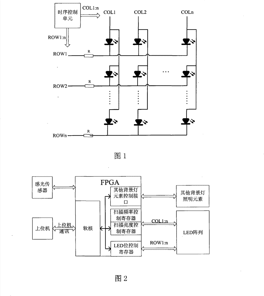
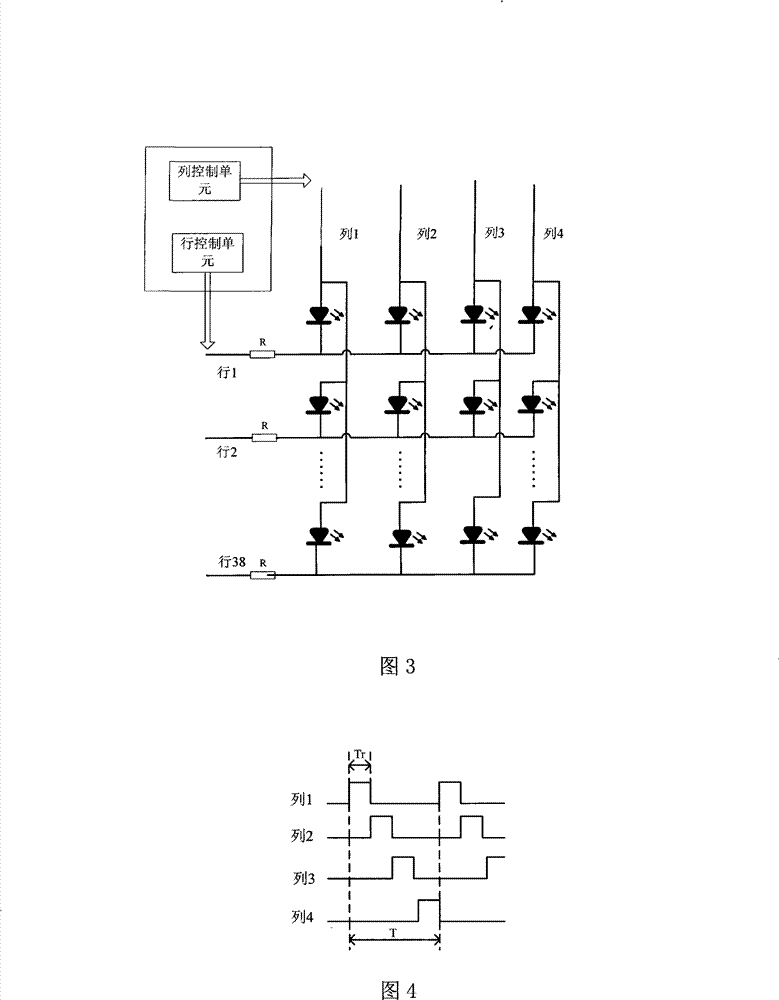
[0029] Such as figure 2 As shown, the intelligent control panel backlight includes an LED array and a programmable controller for controlling the light emission of the LED array, and the programmable controller includes a program control module and a logic control module. The program control module is responsible for receiving and processing external input information and generating LED array control instructions. The logic control module generates array control signals in response to the LED array control instructions to control the LEDs on the corresponding rows and columns of the LED array to emit light. The programmable controller of the present embodiment adopts FPGA, and the program control module is an embedded CPU implemented on FPGA, preferably an embedded soft core, which is a soft control core generated by instantiating logic units inside FPGA. Using FPGA and embedded CPU can easily realize large-scale LED array control. As a program control module, the embedded C...

Embodiment 2

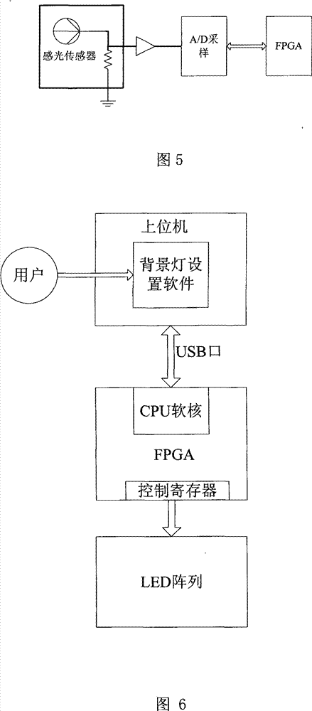
[0041] Compared with Embodiment 1, the difference of this embodiment is that a brightness detection module for detecting ambient light intensity is added. The brightness detection module converts the detected ambient light intensity into a detection signal and then outputs it to the program control module. The program control module generates a corresponding brightness adjustment command according to the detection signal. The logic control module responds to the brightness adjustment command and adjusts its output to be effective. The duty cycle of the signal makes the luminous brightness of the LED array reach a state that is compatible with the ambient light intensity.

[0042] Such as Figure 6 As shown, the brightness detection module adopts a known photosensitive sensor, whose perception characteristics of various wavelengths of light are similar to those of the human eye, and can accurately reflect the light intensity of the environment. The electrical signal output end...


PUM


Abstract

The invention discloses an intelligent background light with control panel, which comprises a light-emitting diode array and a programmable controller for controlling the light-emitting diode array. The programmable controller comprises a program control module and a logic control module, wherein the program control module receives and processes external input information and generates control instructions for the light-emitting diode array, and the logic control module responses to the control instructions to generate array control signals for controlling light-emitting diodes in corresponding row or column of the light-emitting diode array to emit light. The programmable controller is a field programmable gate array, and the program control module is an embedded CPU realized on the field programmable gate array. The invention also discloses a control device of the intelligent background light with control panel. The intelligent background light with control panel resolves the problem of difficult joint between light-emitting diode array controllers of background light and user control programs, supports personalized startup and brightness settings of background light, and supports automatic brightness adjustment of background light, which is characterized by flexible control, simple structure and high integration level.

Description

【Technical field】 [0001] The invention relates to the background light control of the control panel of the ultrasonic image equipment, in particular to an intelligent control panel background light device and its control device. 【Background technique】 [0002] The control panel is usually the most important human-machine interface of ultrasound imaging equipment, and it contains a lot of elements such as buttons, trackballs, sliders and so on. Since the operating environment is usually a dark room, the control panel needs to have its own lighting function. In order to ensure the uniformity of lighting and meet the needs of instructions, usually each button on the control panel needs to be equipped with 1 to 4 LEDs (light emitting diodes, light emitting diodes), and the entire control panel will have as many as 100 to 200 LEDs, and Some of the function keys often need to be controlled independently, therefore, each LED unit on the control panel should be able to be independe...

Claims


Application Information

Patent Timeline
Patent Type & Authority Patents(China)
IPC IPC(8): H05B37/02F21V23/00A61B8/00F21Y101/02F21Y115/10
CPCY02B20/48Y02B20/40
Inventor 姚佳韩乾全刘照泉袁满
Owner SHENZHEN MINDRAY BIO MEDICAL ELECTRONICS CO LTD
Learn More