PWM dimming method and PWM dimming device

A dimming device, PWM signal technology, applied in lighting devices, light sources, electric light sources, etc., can solve the problems of LED light source stroboscopic, increase customer expenses, trouble, etc., achieve smooth and soft dimming effect, avoid stroboscopic Effect

Active Publication Date: 2016-11-23
OPPLE LIGHTING
View PDF4 Cites 4 Cited by
  • Summary
  • Abstract
  • Description
  • Claims
  • Application Information

AI Technical Summary

Problems solved by technology

[0004] Usually, the dimming control circuit in the lighting equipment corresponds to the dimming interface. For example, the dimming switch on the wall has a dimming level that matches the frequency of the PWM signal. However, as people adjust the light The requirements of the environment are getting higher and higher. It is generally recognized that when the PWM frequency is low, the LED light source is prone to flicker. When shooting the LED light source with camera equipment, you will see obvious ripples.
Nowadays, many lighting equipment improve this state by increasing the PWM frequency, but the lighting equipment after changing the frequency cannot match the original dimmer switch. It is very troublesome to reinstall the corresponding dimmer switch, and it will also increase the customer Expenses

Method used


Image

  • PWM dimming method and PWM dimming device
  • PWM dimming method and PWM dimming device
  • PWM dimming method and PWM dimming device

Examples


Embodiment Construction

[0044] A PWM dimming method and a PWM dimming device proposed by the present invention will be further described in detail below in conjunction with the accompanying drawings and specific embodiments.

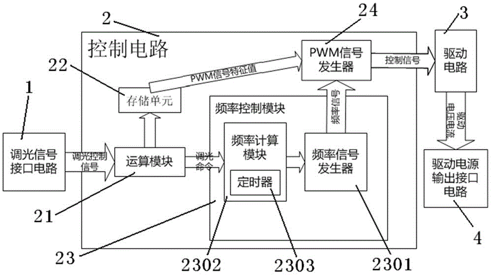
[0045]Please refer to FIG. 2. FIG. 2 is a schematic structural diagram of a preferred embodiment of a PWM dimming device proposed by the present invention. The PWM dimming device includes a dimming signal interface circuit 1, a control circuit 2, and a driving circuit 3. , the drive circuit output interface circuit 4 . The dimming signal interface circuit 1 receives the dimming control signal from the outside and transmits it to the control circuit 2 , the control circuit 2 analyzes the dimming control signal, generates a control signal and transmits it to the driving circuit 3 . The dimming control signal is generated by various interfaces that interact with the user. The interactive interface can be a rotary switch, a button for sub-positions, a remote control or a handheld m...


PUM


Abstract

The invention provides a PWM dimming device, which comprises a dimming signal interface circuit, a drive circuit, a driving power output interface circuit and a control circuit, wherein the dimming signal interface circuit is used for receiving a dimming signal; the drive circuit outputs driving voltage or driving current and the work period is Td; the driving power output interface circuit is connected with a load; the control circuit receives the dimming signal from the dimming signal interface circuit, generates a PWM signal and outputs the PWM signal to the drive circuit; and the control circuit generates the PWM signals with different frequencies during PWM dimming and normal operation of lighting equipment. After the dimming method is adopted, the PWM dimming device can be compatible with dimmer switches at different dimming levels, so that stroboflash can be effectively avoided during normal operation, and meanwhile, a more smooth and softer dimming effect can be obtained

Description

technical field [0001] The invention relates to a PWM dimming method and a PWM dimming device. Background technique [0002] With the rapid development of LED technology, more and more LED light sources have replaced traditional light sources. As we all know, LED has many advantages as a light source, and easy dimming and color adjustment is one of the biggest advantages of LED. With the development and promotion of the Internet of Things and smart homes, there are more and more demands for light source dimming, and the quality requirements for dimming are also getting higher and higher. Therefore, LED dimming technology needs to be continuously improved in order to give full play to its own advantages and follow the development trend of smart home. [0003] At present, the most commonly used LED dimming method is PWM dimming. The principle is to use the PWM signal to control the Buck / Boost switching power supply circuit, and output the corresponding voltage and current va...

Claims


Application Information

Patent Timeline
IPC IPC(8): H05B37/02
Inventor 张俊于同华
Owner OPPLE LIGHTING
Why Eureka
Try Eureka