Pressing tool system for workpiece machining and workpiece lateral end machining and fixing method

A hydraulic system and workpiece technology, which is applied in the field of compression tooling system for automatic processing of elongated workpieces, and the processing field of frogs. It can solve the problems of high labor intensity, low processing efficiency, and difficult correction, etc., and achieve compact structure. , Improve processing efficiency and reduce labor intensity

Active Publication Date: 2016-11-30
翟泉来
View PDF9 Cites 1 Cited by
  • Summary
  • Abstract
  • Description
  • Claims
  • Application Information

AI Technical Summary

Problems solved by technology

[0002] At present, the commonly used compression tooling for processing long strip workpieces, for example, is used in the double-sided processing project of assembled frogs. There is no press-fit unit, and the existing press-fit unit generally consists of a press block and a bottom block, and the press block is placed on the workpiece by means of bolt tension between the two to achieve the purpose of pressing. The problem with this structure and method is that workers need to fix each briquetting block once before each processing, and after processing the single side, it is necessary to remove the tooling, and after changing the direction of the workpiece, the pressing unit can be re-fixed. After processing the other side, after long-term practice by the manufacturer, it was found that this kind of compression tooling and compression method: the labor intensity of the workers is high, the processing efficiency is low, and in order to ensure the processing accuracy, it is difficult to correct

Method used


Image

  • Pressing tool system for workpiece machining and workpiece lateral end machining and fixing method
  • Pressing tool system for workpiece machining and workpiece lateral end machining and fixing method
  • Pressing tool system for workpiece machining and workpiece lateral end machining and fixing method

Examples


Embodiment Construction

[0031] The present invention is described in detail below in conjunction with accompanying drawing and specific embodiment:

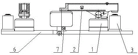
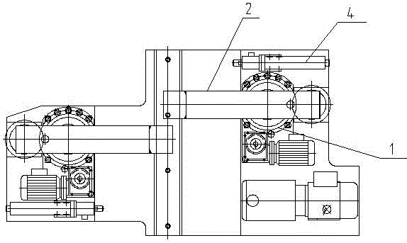
[0032] Such as figure 1 and figure 2 As shown, a compression tooling system for workpiece processing, which includes a compression tooling unit, each group of compression tooling units includes a compression mechanism arranged on one or both sides of a long workpiece, and is characterized in that:

[0033] The pressing mechanism includes a rotating device 1, a pressing arm 2, and a lifting mechanism 3, the rotating device 1 rotates in a horizontal direction, the pressing arm 2 is arranged on the rotating device 1, and one end of the pressing arm 2 is connected to the lifting mechanism 3, The middle part of the pressing arm 2 is hinged with the upper end of the rotating device 1. Utilizing the principle of leverage, the upper lifting mechanism 3 drives the pressing arm 2 to rotate in the vertical direction, and the other end of the pressing arm 2 is pr...


PUM


Abstract

The invention discloses a pressing tool system for long-strip-shaped workpiece machining. The system comprises pressing tool units. Each pressing tool unit comprises a pressing mechanism arranged on one side or two sides of a long-strip-shaped workpiece. Each pressing mechanism comprises a rotary device, a pressing arm and an ejecting mechanism, wherein the rotary device rotates in the horizontal direction, the pressing arm is arranged on the rotary device, one end of the pressing arm makes contact with the ejecting mechanism, the middle of the pressing arm is hinged to the upper end of the rotary device, the ejecting mechanism drives the pressing arm to rotate in the vertical direction by means of the lever principle, and the other end of the pressing arm presses the upper side of the workpiece. The whole pressing tool system for long-strip-shaped workpiece machining comprises the independent pressing tool units and is not limited by the length of the workpiece, cutters of a machining device continuous move, and the system is not hindered by pressing units. The pressing mechanisms can automatically sense and avoid the pressing units. The system and a method greatly improve machining efficiency, compared with traditional manual pressure application, labor intensity of workers is reduced, machining precision and machining quality of products are improved, production cost is reduced, and the system and method are suitable for large-scale application and popularization.

Description

technical field [0001] The invention relates to the technical field of machining, in particular to a pressing tooling system for automatic machining of elongated workpieces, which is mainly used in the machining process of frogs. Background technique [0002] At present, the commonly used compression tooling for processing long strip workpieces, for example, is used in the double-sided processing project of assembled frogs. There is no press-fit unit, and the existing press-fit unit generally consists of a press block and a bottom block, and the press block is placed on the workpiece by means of bolt tension between the two to achieve the purpose of pressing. The problem with this structure and method is that workers need to fix each briquetting block once before each processing, and after processing the single side, it is necessary to remove the tooling, and after changing the direction of the workpiece, the pressing unit can be re-fixed. For the processing of the other si...

Claims


Application Information

Patent Timeline
Patent Type & Authority Applications(China)
IPC IPC(8): B23Q3/00
CPCB23Q3/00B23Q2703/04
Inventor 张国柱
Owner 翟泉来
Why Eureka
Try Eureka