Tool for processing central hole in end part of camshaft

A camshaft and center hole technology, applied in metal processing equipment, metal processing mechanical parts, positioning devices, etc., can solve the problems of inability to accurately control the clamping force, low production efficiency, affecting the force balance of the camshaft, etc. Uncertainty and subjectivity, the effect of improving product processing quality and improving production efficiency

Active Publication Date: 2017-01-04
宁波圣龙智造凸轮轴有限公司
View PDF6 Cites 5 Cited by
  • Summary
  • Abstract
  • Description
  • Claims
  • Application Information

AI Technical Summary

Problems solved by technology

[0003] 1) In the prior art, when machining the center holes at both ends of shaft parts, the clamping surface of the tooling is usually the processed surface, and the clamping state is also determined by manual subjective judgment. Therefore, on the one hand, the clamping Excessive holding force will easily cause deformation of the clamping surface, thereby destroying the surface quality of the camshaft. On the other hand, the clamping force cannot be accurately controlled, and whether it is large or small will affect the force on the camshaft when machining the center holes at both ends of the camshaft. Balanced, resulting in deformation of the entire camshaft;
[0004] 2) In addition, when machining the center holes at both ends of the camshaft, it is usually processed one by one. In other words, the camshaft is clamped on the machine tool vertically or horizontally, and then the two ends are processed step by step, and Only one camshaft can be machined at a time, therefore, the production efficiency is low

Method used


Image

  • Tool for processing central hole in end part of camshaft
  • Tool for processing central hole in end part of camshaft
  • Tool for processing central hole in end part of camshaft

Examples


Embodiment Construction

[0029] The present invention will be further described in detail below in conjunction with the drawings and specific embodiments.

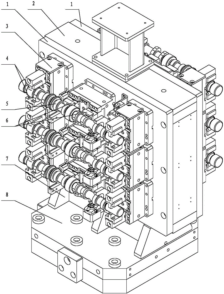
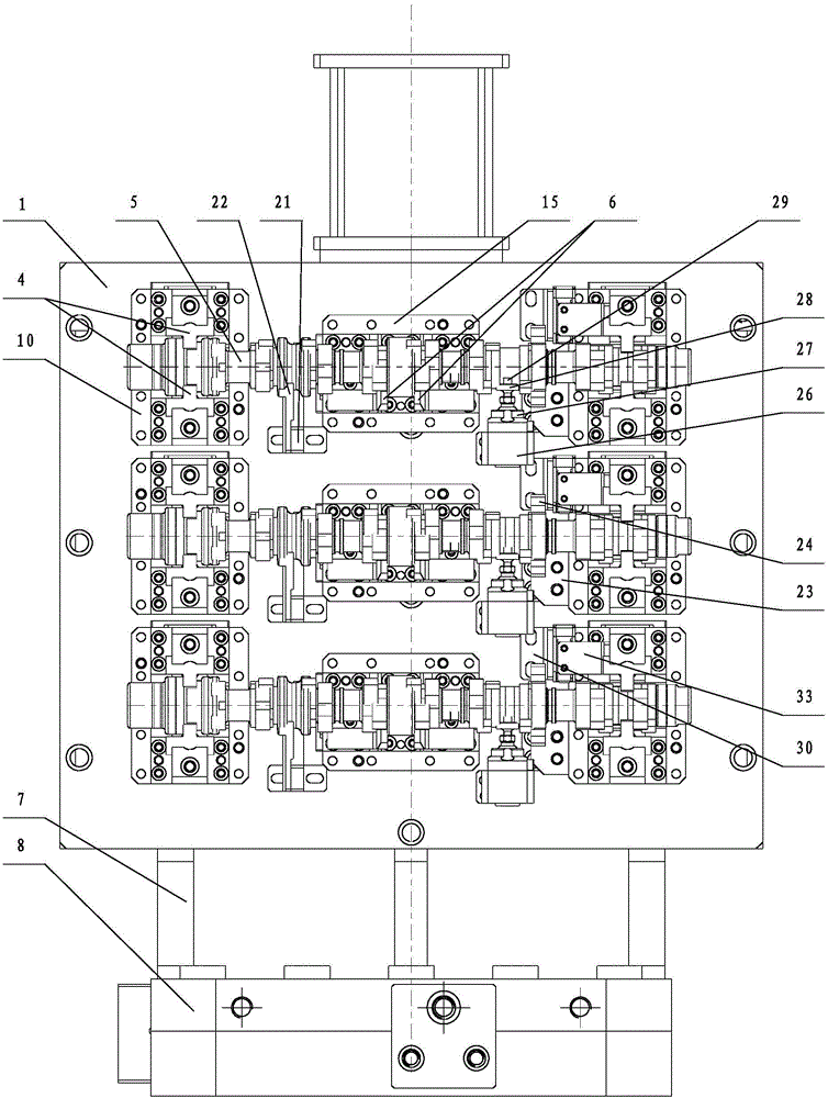
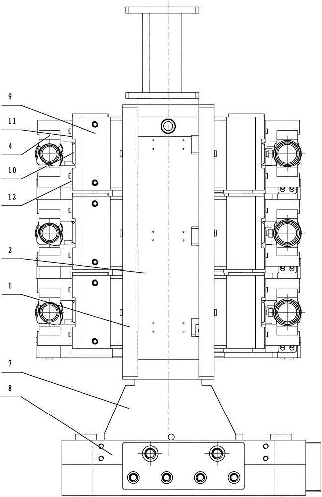
[0030] by Figure 1 ~ Figure 6 The shown structural diagram of the tool for machining the center hole of the camshaft end of the present invention shows that it includes a support frame assembly, a plurality of clamping units 3, a pre-positioning device and a gas inspection device. The lower end of the support frame assembly is connected to the worktable of the machine tool through a rotary cylinder, and each clamping unit 3 clamps and fixes a camshaft 5 and the camshafts 5 are placed horizontally. The plurality of clamping units 3 are arranged in parallel at equal distances from top to bottom and are respectively connected symmetrically on the two end surfaces of the support frame assembly. Each clamping unit 3 is equipped with a pre-positioning device and a gas detection device, and the pre-positioning device and the gas detection device are both ...


PUM


Abstract

The invention discloses a tool for processing a center hole in an end shaft of a camshaft. The tool comprises a supporting frame assembly, a plurality of clamping units (3), pre-positioning devices and gas inspecting devices; the lower end of the supporting frame assembly is connected onto a workbench of a machine tool through a rotary cylinder; each clamping unit (3) is used for clamping one camshaft (5) which is horizontally arranged; the plurality of the clamping units (3) are in parallel arranged at equal distance from top to bottom, and are symmetrically connected onto two end surfaces of the supporting frame assembly; each clamping unit (3) is equipped with one pre-positioning device and one gas inspecting device; and the pre-positioning devices and the gas inspecting devices are connected onto the supporting frame assembly. With the adoption of the structure, force borne on the camshaft is more balanced when the central hole is processed in the end part of the camshaft, so that deformation of the camshaft is avoided, and product processing quality is improved.

Description

Technical field [0001] The invention relates to the technical field of camshaft processing, in particular to a tool for processing a center hole at the end of a camshaft. Background technique [0002] Traditional camshaft manufacturing methods are diverse, including steel pipe internal expansion method, internal hydraulic pressure method, hot sleeve method, powder metallurgy method, knurled connection method and press fitting method. Regardless of which method is manufactured, the camshaft needs to be processed by finishing to meet the machining requirements of each camshaft, such as machining a center hole on the end of the camshaft. Therefore, when processing these center holes, the camshaft is usually installed on a machine tool through a fixture for processing. In the prior art, most companies use horizontal machining centers to process the center holes of camshafts. For example, the patent for "Camshaft Milling End Face Punching Tooling" published on the website of the Sta...

Claims


Application Information

Patent Timeline
Patent Type & Authority Applications(China)
IPC IPC(8): B23Q3/08
CPCB23Q3/082
Inventor 王晨余星徐宁曾夏刚龙周杰朱瑞罗玉龙
Owner 宁波圣龙智造凸轮轴有限公司
Why Eureka
Try Eureka