Induction cooker wire coil assembly, induction cooker and electromagnetic heating assembly

A technology for heating components and induction cookers, which is applied to electric heating fuels, lighting and heating equipment, induction heating, etc., can solve the problems of increasing production costs, disadvantages, and unsuitability for heating of pots and pans, so as to increase production costs, reduce heating efficiency, The effect of reducing the power consumption of the device

Active Publication Date: 2017-01-04
FOSHAN SHUNDE MIDEA ELECTRICAL HEATING APPLIANCES MFG CO LTD +1
View PDF6 Cites 2 Cited by
  • Summary
  • Abstract
  • Description
  • Claims
  • Application Information

AI Technical Summary

Problems solved by technology

[0002] In the related art, the induction cooker is widely used in family life because of its high heating efficiency, simple heating control method, low price and high safety in use. However, the electromagnetic radiation generated by the induction cooker during the heating process has adverse effects on users. Impact, in order to reduce the leakage of electromagnetic radiation, the coating process is usually added in the preparation process of the induction cooker to form a metal shielding net on the traditional induction cooker shell, but this will undoubtedly increase the production cost. In addition, in order to improve the electromagnetic heating efficiency, Designers add a magnetic structure to the traditional induction cooker to guide the electromagnetic radiation. However, the fixed magnetic structure is not suitable for heating all pots, which is not conducive to meeting the various cooking needs of users.

Method used


Image

  • Induction cooker wire coil assembly, induction cooker and electromagnetic heating assembly
  • Induction cooker wire coil assembly, induction cooker and electromagnetic heating assembly
  • Induction cooker wire coil assembly, induction cooker and electromagnetic heating assembly

Examples


Embodiment Construction

[0042] In order to understand the above-mentioned purpose, features and advantages of the present invention more clearly, the present invention will be further described in detail below in conjunction with the accompanying drawings and specific embodiments. It should be noted that, in the case of no conflict, the embodiments of the present application and the features in the embodiments can be combined with each other.

[0043]In the following description, many specific details are set forth in order to fully understand the present invention. However, the present invention can also be implemented in other ways than described here. Therefore, the protection scope of the present invention is not limited by the specific implementation disclosed below. Example limitations.

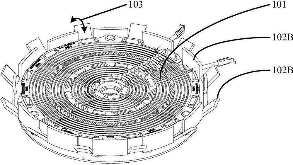
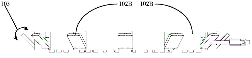
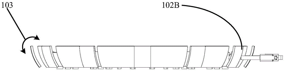
[0044] Combine below Figure 1 to Figure 5 The structures of the coil assembly of the induction cooker, the induction cooker and the electromagnetic heating device according to the embodiment of the present i...


PUM


Abstract

The invention provides an induction cooker wire coil assembly, an induction cooker and an electromagnetic heating assembly. The induction cooker wire coil assembly comprises an electromagnetic wire coil and variable field-controlled magnetic sheet structures, wherein the electromagnetic wire coil is used for generating electromagnetic radiation; the variable field-controlled magnetic sheet structures are arranged in the peripheral zone of the electromagnetic wire coil, are used for controlling the electromagnetic radiation to be guided and distributed, and comprise at least two field-controlled magnetic sheets, and a microcontroller; the at least two field-controlled magnetic sheets are detachably arranged in the peripheral zone of the electromagnetic wire coil; the relative position between an arbitrary field-controlled magnetic sheet in the at least two field-controlled magnetic sheets and the electromagnetic wire coil, and an included angle between an arbitrary field-controlled magnetic sheet and an plumb line are adjusted according to a field-controlled instruction; and the microcontroller is connected between the at least two field-controlled magnetic sheets and is used for generating the field-controlled instruction. Through the technical scheme, guided control for electromagnetic radiation is achieved, and leakage of electromagnetic radiation is reduced.

Description

technical field [0001] The invention relates to the technical field of household appliances, and more specifically, to an induction cooker coil assembly, an induction cooker and an electromagnetic heating assembly. Background technique [0002] In the related art, the induction cooker is widely used in family life because of its high heating efficiency, simple heating control method, low price and high safety in use. However, the electromagnetic radiation generated by the induction cooker during the heating process has adverse effects on users. Impact, in order to reduce the leakage of electromagnetic radiation, the coating process is usually added in the preparation process of the induction cooker to form a metal shielding net on the traditional induction cooker shell, but this will undoubtedly increase the production cost. In addition, in order to improve the electromagnetic heating efficiency, Designers add magnetic structures to traditional induction cookers to guide ele...

Claims


Application Information

Patent Timeline
Patent Type & Authority Applications(China)
IPC IPC(8): F24C7/06F24C7/08H05B6/36
Inventor 张贵林
Owner FOSHAN SHUNDE MIDEA ELECTRICAL HEATING APPLIANCES MFG CO LTD
Why Eureka
Try Eureka