Rotor dynamic balancing measuring method based on steady state incentive and device thereof

A rotor dynamic balance and measurement method technology, applied in the field of measurement and testing, can solve the problems of reducing rotor life, rotor vibration, uneven rotor quality, etc., and achieve the effect of reducing the number of startups and reducing costs

Active Publication Date: 2017-01-04
北京东方振动和噪声技术研究所
View PDF6 Cites 9 Cited by
  • Summary
  • Abstract
  • Description
  • Claims
  • Application Information

AI Technical Summary

Problems solved by technology
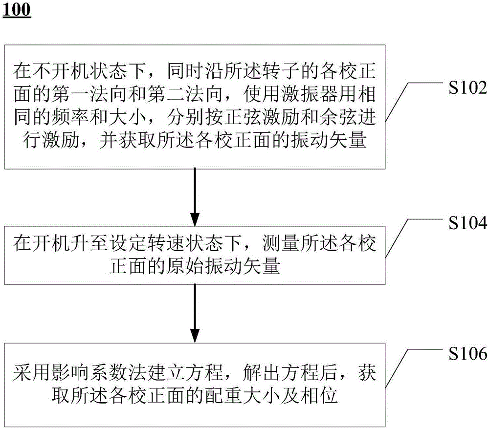
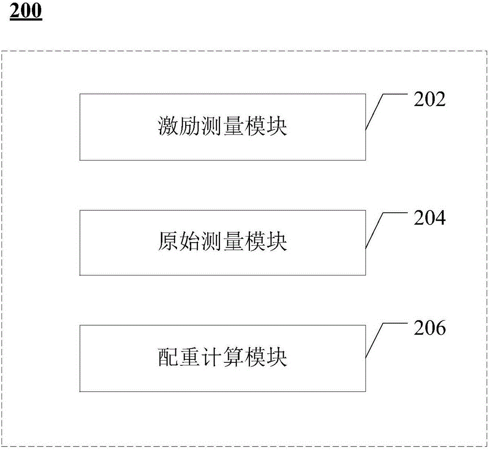
[0002] During the operation of rotating machinery, if the quality of the rotor is uneven, centrifugal force will be generated during operation, which will cause rotor vibration and reduce the life of the rotor.

Method used


Image

  • Rotor dynamic balancing measuring method based on steady state incentive and device thereof
  • Rotor dynamic balancing measuring method based on steady state incentive and device thereof
  • Rotor dynamic balancing measuring method based on steady state incentive and device thereof

Examples


Embodiment Construction

[0031] Example embodiments will now be described more fully with reference to the accompanying drawings. Example embodiments may, however, be embodied in many forms and should not be construed as limited to the examples set forth herein; rather, these embodiments are provided so that this disclosure will be thorough and complete and will fully convey the concept of example embodiments to those skilled in the art. The described features, structures, or characteristics may be combined in any suitable manner in one or more embodiments. In the following description, numerous specific details are provided in order to give a thorough understanding of embodiments of the present disclosure. However, those skilled in the art will appreciate that the technical solutions of the present disclosure may be practiced without one or more of the specific details being omitted, or other methods, components, devices, steps, etc. may be adopted. In other instances, well-known technical solution...


PUM


Abstract

The invention provides a rotor dynamic balancing measuring method based on steady state incentive and a device thereof. The method consists of the following steps: with regard to every rectification side, under the state of power off, using a vibration exciter with the same frequency and size to carry on sinusoidal excitation and cosine excitation respectively along the first normal direction and the second normal direction of the rectification sides of the rotors, and then obtaining the vibration vectors of every rectification side; according to the size of the exciting force and the rotor radius, calculating the influence coefficient of the fixed frequency relative to the revolving speed; measuring the original vibration vectors of the rectification sides under the state when the power is on and the rotor has risen to the setting speed; establishing an equation through the influence coefficient, and after solving the equation, obtaining the balance weight and the phase position of all the rectification sides. According to this rotor dynamic balancing measuring method based on steady state incentive, the cost for measuring the rotor dynamic balancing can be lowered.

Description

technical field [0001] The present disclosure relates to the technical field of measurement and testing, in particular, to a method and device for measuring rotor dynamic balance based on a steady-state excitation method. Background technique [0002] During the operation of rotating machinery, if the quality of the rotor is uneven, centrifugal force will be generated during operation, which will cause rotor vibration and reduce the life of the rotor. In order to prolong the service life of the rotor, it is usually possible to add a counterweight with a specific mass at the preset position of the outer ring of the rotor plane to completely offset this part of the centrifugal force, which is the dynamic balancing process. For a multi-faceted rotor, the unbalance of each face will affect the vibration of multiple faces, so it is necessary to add counterweights of appropriate size and position on multiple faces of the rotor for dynamic balance. The dynamic balancing of automob...

Claims


Application Information

Patent Timeline
Patent Type & Authority Applications(China)
IPC IPC(8): G01M1/16
CPCG01M1/16
Inventor 刘进明
Owner 北京东方振动和噪声技术研究所
Why Eureka
Try Eureka