Symmetrical cone rolling parts and symmetrical cone rolling devices

A cone-shaped and symmetrical technology, which is applied in the field of metal material processing, can solve the problems of inconsistent torsional deformation force of rollers, uneven linear speed of plates, and insufficient detailed and in-depth research, so as to improve processing efficiency, shorten processing time, and improve processing coverage. wide range of effects

Active Publication Date: 2018-07-03
HOHAI UNIV +2
View PDF6 Cites 0 Cited by
  • Summary
  • Abstract
  • Description
  • Claims
  • Application Information

AI Technical Summary

Problems solved by technology

But the disadvantage is that the rolling times are higher and the service life of the ball is shorter
[0004] In addition, South China University of Technology adopts the method of rotary pressing cylindrical roller rolling to obtain surface structure refinement and strengthening. This method is a strengthening method of surface rotary rolling and has achieved good results. For the plate, due to the uneven linear velocity relative to the plate in the direction of the roller generatrix, the force of the roller torsional deformation is inconsistent, so the loss of the mold is relatively large
[0005] It can be seen that the above rolling methods are mainly limited to the processing of shafts and sleeve parts. For the efficient and economical rolling of large flat surfaces and the relative motion of blanks, the current research is not detailed enough.

Method used


Image

  • Symmetrical cone rolling parts and symmetrical cone rolling devices
  • Symmetrical cone rolling parts and symmetrical cone rolling devices
  • Symmetrical cone rolling parts and symmetrical cone rolling devices

Examples


Embodiment 1

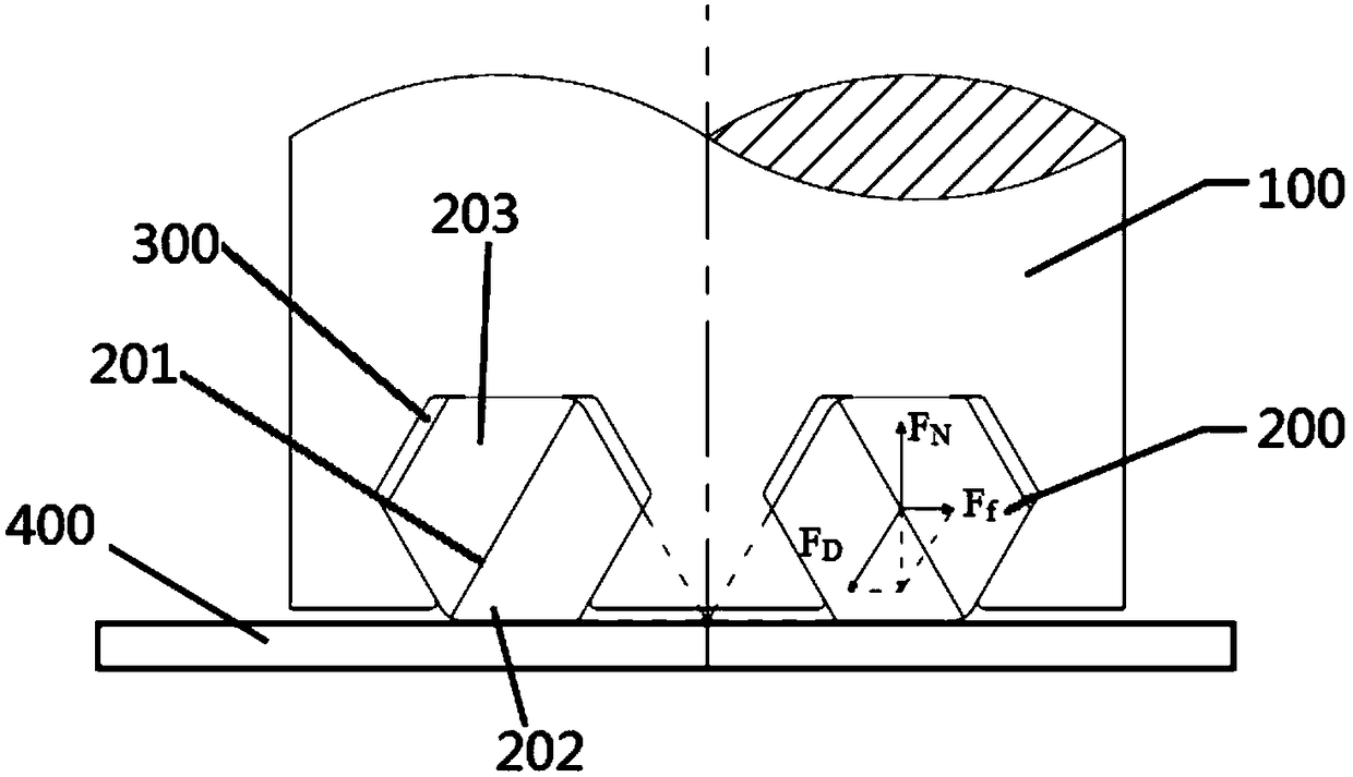
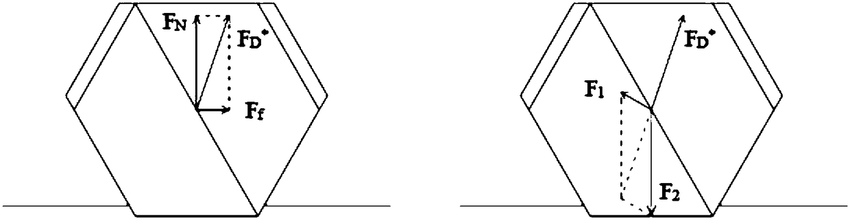
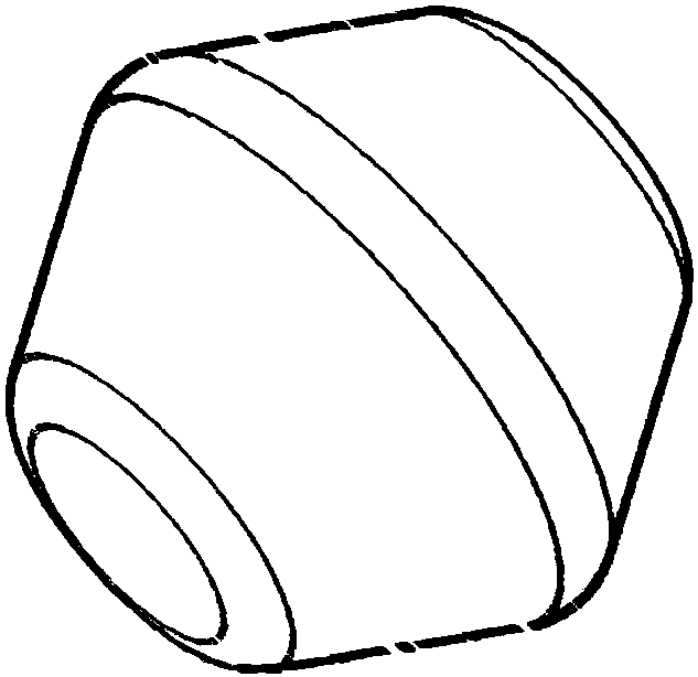
[0030] like Figure 1-4 As shown, the present symmetrical cone rolling part includes a rotary pressing body 100 and a roller indenter 200. A slot 300 is provided in the rotary pressing body, and the roller pressing head 200 is arranged in the slot of the rotary pressing body. The sub-indenter is integrally formed, and its appearance is composed of two truncated conical rollers of the same size on the bottom surface 201. The rotating surface close to the axis of the rotary pressing body is the working surface 202, and the other surface is the supporting surface 203. There are two sub-indenters, the axes of the two roller indenters and the axis of the rotating pressing body are in the same plane, and in this plane, the axes of the two roller pressing heads are aligned with the axis of the rotating pressing body. The axis line is axisymmetrically arranged. The busbar at the bottom of the working surface of the two roller indenters nested in the rotary press body is located outsid...

Embodiment 2

[0033] like Figure 5-6 As shown, the symmetrical cone rolling device includes a rotary pressing body 100, a roller indenter, a rotating pressing body driving device, a bed body, and a bed body driving device. In the embedded groove of the rotary pressing body, the roller press head is integrally formed. Its appearance is two truncated conical rollers of the same size assembled on the bottom surface, and the turning surface close to the axis of the rotating pressing body is the working surface. , the other side is the support surface, there are two roller indenters, the axes of the two roller indenters and the axis of the rotating pressing body are in the same plane, and in this plane, the two roller indenters The axis line of the rotary press body is arranged symmetrically with the axis line of the rotary press body. The busbar at the bottom of the working surface of the two roller indenters nested in the rotary press body is located outside the rotary press body and is in a ...

Embodiment 3

[0041] like Figure 7-11 As shown, the present symmetrical cone rolling part includes a rotating pressing body 100 and a roller indenter 200. The rotating pressing body includes a cage 15, a supporting shaft 16, a shaft sleeve 17, a shaft pin 18, and a connecting block 19. , rolling knife body 20, spring 21, reaming hole bolts 22,28, end straight connector 23; the support shaft 16 is cylindrical, and the middle part of the support shaft protrudes to form two bosses 161, wherein the boss below It fits with the cage 15, the upper boss is in contact with the spring 21, the cage 15 and the support shaft 16 are fixed by the shaft pin 18, the shaft sleeve 17 is set outside the support shaft 16, and the support shaft 16 can be connected by the spring 21 Apply pressure, the connecting block 19 is set above the support shaft 16, the rolling knife body 20 is set above the shaft sleeve 17, and the rolling knife body 20 and the shaft sleeve 17 are fixed by reaming hole bolts 28, and the r...


PUM

PropertyMeasurementUnit
hardnessaaaaaaaaaa
radiusaaaaaaaaaa
hardnessaaaaaaaaaa

Abstract

The invention discloses a symmetric cone rolling part. Cone revolving roller pressure heads are adopted. The symmetric cone rolling part comprises a rotating pressure body and the roller pressure heads. The rotating pressure body comprises a retainer, a supporting shaft, a shaft sleeve, a shaft pin, a connecting fixture block, a rolling tool body, a spring and a hinged bolt; and each of the roller pressure heads is integrally molded and is arranged in a caulking groove of the rotating pressure body, and the appearance of each of the roller pressure heads is formed by splicing two conical rollers with the same size on a bottom surface. The invention also discloses a symmetric cone rolling device comprising the rolling part. According to the symmetric cone rolling device, the rotating pressure body drives the revolving roller pressure heads nested in the rotating pressure body to roll a metal surface in a reciprocated way at high speed, and a strain strengthening effect is generated on the metal surface, so that the metal surface is strengthened; a cone revolving roller is divided into a supporting surface and a working surface, the supporting surface is used for transferring the positive pressure of the pressure body to the working surface, approximately pure rolling is remained between the working surface and a test piece, and the contact friction between the working surface and the test piece is avoided due to the existence of a reserved gap between the working surface and the pressure body, so that the service life of a die can be effectively prolonged.

Description

technical field [0001] The invention relates to a symmetrical cone rolling part and a symmetrical cone rolling device, belonging to the field of metal material processing. Background technique [0002] The surface rolling strengthening of metal materials means that a certain thickness of hardened and deformed layer is formed on the surface of the material matrix, and the hardness and wear resistance of the metal surface can be effectively improved. Surface rolling strengthening technology has many advantages: rolling strengthening changes the physical state of the surface of metal materials without changing the chemical composition of the material; the tools and processes used for surface rolling are relatively simple, and the processing efficiency is high; The cutting process will not produce waste chips and waste liquid during the process, and has less pollution to the environment, which is in line with the development concept of "green manufacturing". This technology has...

Claims


Application Information

Patent Timeline
Patent Type & Authority Patents(China)
IPC IPC(8): B23P9/02
CPCB23P9/02
Inventor 宋丹游凯朱婷蒋金洋艾志勇江静华马爱斌
Owner HOHAI UNIV
Why Eureka
Try Eureka