Back pressure valve

A mud backflow and valve body technology, applied in wellbore/well components, earthwork drilling, wellbore flushing, etc., can solve problems such as large amount of engineering, safety accidents, valve core failure, etc., to reduce grouting costs and eliminate Safety accidents and the effect of eliminating safety hazards

Inactive Publication Date: 2017-03-08
CHENGDU ZHUOXIN IND
View PDF10 Cites 5 Cited by
  • Summary
  • Abstract
  • Description
  • Claims
  • Application Information

AI Technical Summary

Problems solved by technology

However, the prior art represented by this patent document all has defects: when drilling, every time a part of the drill pipe is put down, it is necessary to connect the grouting device to pour mud into the drill pipe, and then remove the grouting device after filling. Putting in the next section of drill pipe, and repeating this to complete the drilling action, the engineering volume is very large, time-consuming and laborious, and a large amount of mud needs to be poured, and the cost of grouting is high
A spring is installed between the spool and the base of the back pressure valve. The spring is sleeved on the stem of the spool. One end of the spring is connected to the base and the other end is connected to the tapered block of the spool. Due to the diameter of the stem Smaller, back pressure. During long-term use, the valve core moves up and down, and the spring will continue to return and compress. The spring is easily deformed by excessive extrusion, which makes the tapered block of the valve core unable to be fast and effective. The accurate reset of the valve seat cannot fit well with the cone surface of the valve seat, and the purpose of blocking the water eye cannot be achieved; and when the spring is compressed and reset, the spring swings and continuously hits the valve stem of the valve core, causing the valve stem to break , the spool loses its function, causing the mud to spray back, resulting in extremely serious safety accidents

Method used


Image

  • Back pressure valve
  • Back pressure valve
  • Back pressure valve

Examples


Embodiment 1

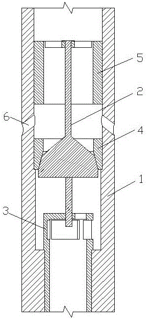
[0038] see figure 1 , a back pressure valve, including a valve body 1, a valve core 2, a support seat 3 and a valve seat 4 arranged in the valve body 1, the support seat 3 is located below the valve seat 4, and the valve body 1 is provided with a piston 5. The piston 5 is set on the valve core 2, the valve body 1 has a mud return hole 6, the mud return hole 6 is located between the valve seat 4 and the piston 5, the mud return hole 6 and the valve body 1 The inner cavity is connected.

[0039] This embodiment is the most basic implementation. A piston is arranged in the valve body, and the piston is sleeved on the valve core. A mud return hole is opened on the valve body. The mud return hole is located between the valve seat and the piston. The mud return hole and the valve body The inner cavity is connected. By setting up a mud return hole on the valve body and connecting the mud return hole with the inner cavity of the valve body, when drilling, by lowering the drilling too...

Embodiment 2

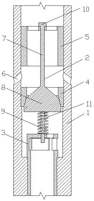
[0041] see figure 2 , a back pressure valve, including a valve body 1, a valve core 2, a support seat 3 and a valve seat 4 arranged in the valve body 1, the support seat 3 is located below the valve seat 4, and the valve body 1 is provided with a piston 5. The piston 5 is set on the valve core 2, the valve body 1 has a mud return hole 6, the mud return hole 6 is located between the valve seat 4 and the piston 5, the mud return hole 6 and the valve body 1 The inner cavity is connected.

[0042] Described spool 2 comprises upper valve stem 7, conical block 8 and lower valve stem 9 successively from top to bottom, and the upper end of upper valve stem 7 is provided with fixing nut 10, and the lower end is connected with the small end of conical block 8, and the lower end is connected with the small end of conical block 8. One end of the valve rod 9 is connected with the large end of the conical block 8, and the other end extends into the support seat 3.

[0043] The valve seat...

Embodiment 3

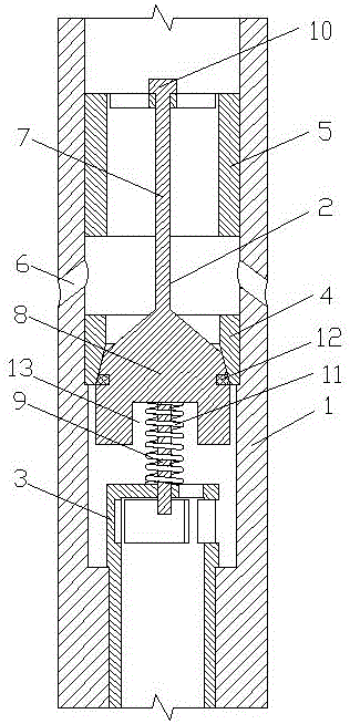
[0049] see image 3 , a back pressure valve, including a valve body 1, a valve core 2, a support seat 3 and a valve seat 4 arranged in the valve body 1, the support seat 3 is located below the valve seat 4, and the valve body 1 is provided with a piston 5. The piston 5 is set on the valve core 2, the valve body 1 has a mud return hole 6, the mud return hole 6 is located between the valve seat 4 and the piston 5, the mud return hole 6 and the valve body 1 The inner cavity is connected.

[0050] Described spool 2 comprises upper valve stem 7, conical block 8 and lower valve stem 9 successively from top to bottom, and the upper end of upper valve stem 7 is provided with fixing nut 10, and the lower end is connected with the small end of conical block 8, and the lower end is connected with the small end of conical block 8. One end of the valve rod 9 is connected with the large end of the conical block 8, and the other end extends into the support seat 3.

[0051] The valve seat ...


PUM


Abstract

The invention discloses a back pressure valve and belongs to the technical field of drilling equipment. The back pressure valve comprises a valve body, a valve element, a bearing seat and a valve seat and is characterized in that the bearing seat and the valve seat are arranged in the valve body, the bearing seat is located below the valve seat, a piston is arranged in the valve body and sleeves the valve element, a slurry return hole is formed in the valve body and located between the valve seat and the piston, and the slurry return hole is communicated with the inner cavity of the valve body. The back pressure valve has the advantages that slurry in a well can be automatically filled into a drill pipe, a slurry filling device needs not to be connected to fill the slurry into the drill pipe after each drill pipe part is descended, work amount is reduced greatly, time and labor are saved, slurry filing cost is lowered effectively, the slurry in the well can be prevented from being reversely sprayed into drill pipe through the inner cavity of the valve body, and safety accidents are avoided.

Description

technical field [0001] The invention relates to the technical field of drilling equipment, in particular to a back pressure valve. Background technique [0002] The back pressure valve is a device for preventing internal blowout during the drilling process. It is a check valve. The back pressure valve can effectively prevent the formation fluid from entering the drilling tool through the water hole of the drill bit. The existing back pressure valve mainly includes a valve body, a support seat, a valve core and a valve seat. Its structural principle is that there is a conical movable valve core in the water eye of the tool. When installing, its large end faces down and the small end faces upward. When the mud flows from the water eye to the top and bottom, the flow resistance is small and it can pass through smoothly; When the mud flows from the bottom to the top of the drill string, the large end receives a greater thrust, which prompts the conical movable device to move up...

Claims


Application Information

Patent Timeline
Patent Type & Authority Applications(China)
IPC IPC(8): E21B21/10
CPCE21B21/10
Inventor 陈伦俊池振华邹益文卢伟
Owner CHENGDU ZHUOXIN IND
Why Eureka
Try Eureka