Centrifugal fan

A centrifugal fan and air intake technology, which is applied in mechanical equipment, machines/engines, liquid fuel engines, etc., can solve the problems of low air supply efficiency, reduced air volume, and increased air supply resistance, and achieves reasonable structural layout and air supply. The effect of large volume and reasonable air supply

Active Publication Date: 2017-03-22
HAIER SMART HOME CO LTD
View PDF5 Cites 10 Cited by
  • Summary
  • Abstract
  • Description
  • Claims
  • Application Information

AI Technical Summary

Problems solved by technology

This will increase the cost, and in some special occasions, due to space constraints, multiple fans cannot be installed, which will affect production or use. In addition, the installation of external joints not only increases the cost but also greatly increases the air supply resistance, reducing the air volume. , the air supply efficiency is low, and the air supply volume of each joint cannot be controlled

Method used


Image

  • Centrifugal fan
  • Centrifugal fan
  • Centrifugal fan

Examples


Embodiment Construction

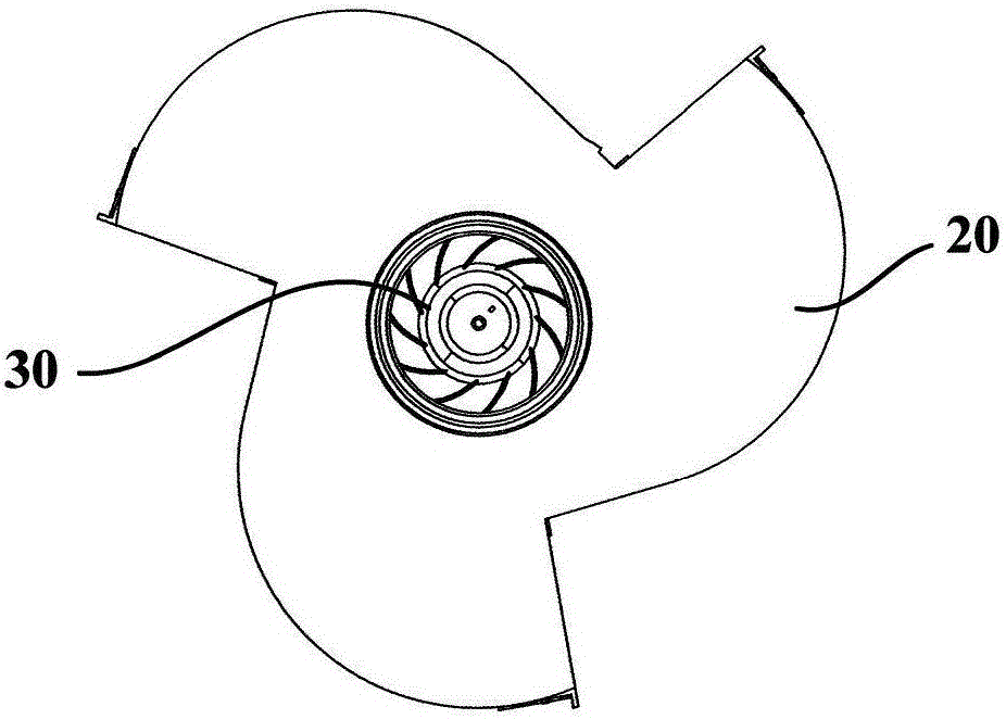
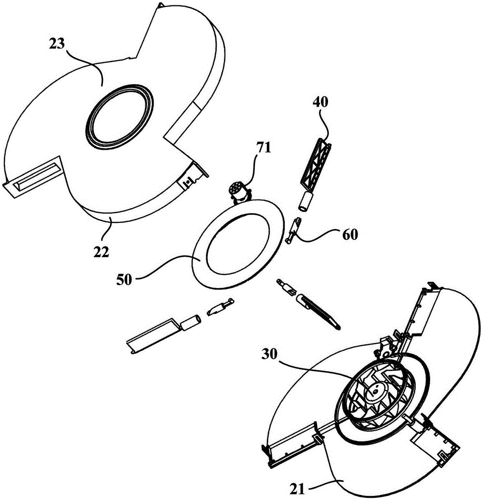
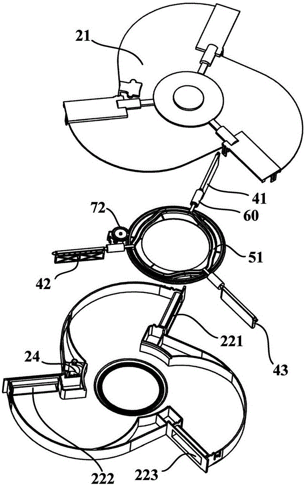
[0041] figure 1 is a schematic structural diagram of a centrifugal fan according to an embodiment of the present invention; figure 2 and image 3 are schematic exploded views of a centrifugal fan according to an embodiment of the present invention; Figure 4 is a schematic partial structural diagram of a centrifugal fan according to an embodiment of the present invention. Such as Figure 1 to Figure 4 As shown, the embodiment of the present invention provides a centrifugal fan. The centrifugal fan may include a casing 20 , a wind wheel 30 , a plurality of flaps 40 , a rotating member 50 and a transmission mechanism 60 .

[0042] The case 20 may have a bottom case part 21 , a peripheral wall part 22 and a cover part 23 . Specifically, the bottom case part 21 may be in the shape of a plate, and the cover part 23 may also be in the shape of a plate. The peripheral wall portion 22 can be integrally formed with the cover portion 23 , that is, the peripheral wall portion 22 e...


PUM


Abstract

The invention provides a centrifugal fan. The centrifugal fan comprises a shell, a wind wheel, multiple wind door baffle plates, a rotating piece, and a transmission mechanism, wherein an intake space communicated with an intake port and multiple exhaust wind ways bent to extend are defined in the shell; the wind wheel is configured to accelerate air currents to flow in the shell from the intake port and to flow out of the shell by one or more of the multiple exhaust ports; the multiple wind door baffle plates respectively adjust the exhaust areas of the multiple exhaust ports or the exhaust wind ways; and the transmission mechanism is configured to transfer a rotating motion of the rotating piece to the multiple wind door baffle plates, so that the multiple wind door baffle plates move to respectively corresponding shielding positions. The centrifugal fan can drive the wind door baffle plates to rotate through rotation of the rotating piece to controllably shield the multiple exhaust ports so as to realize synchronous air supply in multiple directions, and can select the exhaust directions and adjust the exhaust quantities of all the exhaust ports to realize reasonable air supply.

Description

technical field [0001] The invention relates to the technical field of fan air supply, in particular to a centrifugal fan. Background technique [0002] Existing centrifugal fans are provided with only one air outlet. When it is necessary to supply air to two or more different directions or multiple positions, it is necessary to install multiple fans or add external joints matching the fans to meet the needs of different directions or locations. The demand for air supply in multiple locations. This will increase the cost, and in some special occasions, due to space constraints, multiple fans cannot be installed, which will affect production or use. In addition, the installation of external joints not only increases the cost but also greatly increases the air supply resistance, reducing the air volume. , the air supply efficiency is low, and the air supply volume of each joint cannot be controlled. Contents of the invention [0003] An object of the present invention is t...

Claims


Application Information

Patent Timeline
Patent Type & Authority Applications(China)
IPC IPC(8): F04D29/42F04D29/46F04D29/66
CPCF04D29/4246F04D29/464F04D29/663F04D29/666F04D29/667
Inventor 费斌程学丽刘金林尚亚洲
Owner HAIER SMART HOME CO LTD
Why Eureka
Try Eureka