centrifugal fan

A centrifugal fan and wind wheel technology, applied in the direction of mechanical equipment, electromechanical devices, control of mechanical energy, etc., can solve the problems of affecting production or use, increasing air supply resistance, and low air supply efficiency, so as to reduce air supply noise and reasonable air supply The effect of large wind and air supply volume

Active Publication Date: 2022-03-25
HAIER SMART HOME CO LTD
View PDF10 Cites 0 Cited by
  • Summary
  • Abstract
  • Description
  • Claims
  • Application Information

AI Technical Summary

Problems solved by technology

This will increase the cost, and in some special occasions, due to space constraints, multiple fans cannot be installed, which will affect production or use. In addition, the installation of external joints not only increases the cost but also greatly increases the air supply resistance, reducing the air volume. , low air supply efficiency

Method used


Image

  • centrifugal fan
  • centrifugal fan
  • centrifugal fan

Examples


Embodiment Construction

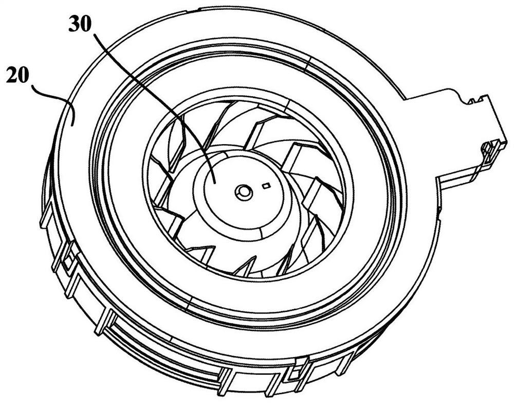
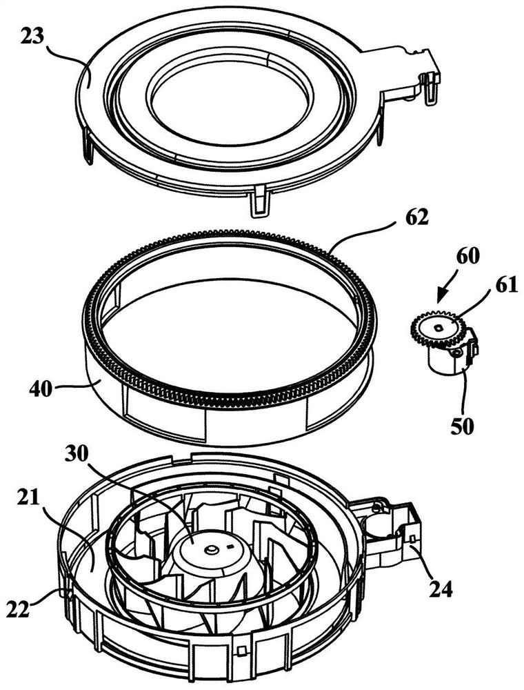
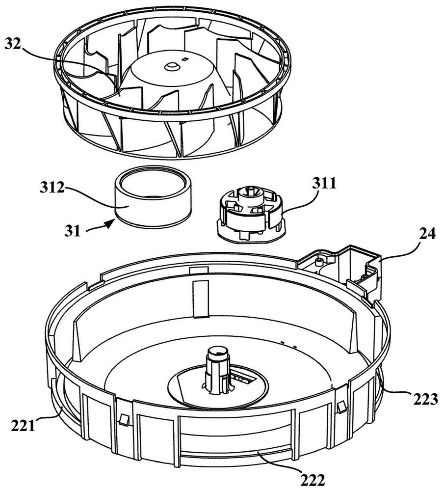
[0039] figure 1 is a schematic structural diagram of a centrifugal fan according to an embodiment of the present invention; figure 2 and image 3 They are a schematic exploded view and a schematic exploded view of a partial structure of a centrifugal fan according to an embodiment of the present invention, respectively. like Figure 1 to Figure 3 As shown, an embodiment of the present invention provides a centrifugal fan. The centrifugal fan may include a casing 20 , a fan wheel assembly 30 , a blowing control device 40 , a regulating motor 50 and a transmission mechanism 60 .

[0040] The case 20 may have a bottom case part 21 , a peripheral wall part 22 and a cover part 23 . Specifically, the bottom case portion 21 may be in the shape of a plate, the peripheral wall portion 22 may be in the shape of a cylinder, and the cover portion 23 may be a cover plate. The peripheral wall portion 22 may be integrally formed with the bottom case portion 21 , that is, the peripheral...


PUM


Abstract

The invention provides a centrifugal fan. The centrifugal fan includes: a casing, an air inlet is opened on the cover, and a plurality of air outlets are opened on the surrounding wall; a wind wheel assembly, which has a wind wheel motor and a plurality of fan blades; an air supply control device, which is rotatably arranged in the casing, and has one or more shielding parts; the adjusting motor is arranged on the radially outer side of the surrounding wall; Each shielding part is rotated to different rotation positions to completely cover, partially cover or fully expose each air outlet, thereby adjusting the respective air outlet areas of the multiple air outlets. The centrifugal fan can controllably shield multiple air outlets through the rotation of the air supply control device, so as to realize simultaneous air supply to multiple directions / multiple places, and can select the air outlet direction / air supply place and Adjust the air volume of each air outlet to achieve a reasonable air supply.

Description

technical field [0001] The invention relates to the technical field of fan air supply, in particular to a centrifugal fan. Background technique [0002] The existing centrifugal fan is only provided with one air outlet. When air needs to be supplied to two or more different directions or multiple positions, it is necessary to set up multiple fans or add external joints matched with the fans to meet the requirements of different directions or multiple positions. The need for air supply at multiple locations. This leads to an increase in cost, and in some special occasions, multiple fans cannot be installed due to space constraints, which will affect production or use. In addition, the installation of external joints not only increases the cost, but also greatly increases the air supply resistance and reduces the air volume. , the air supply efficiency is low. SUMMARY OF THE INVENTION [0003] One object of the present invention is to overcome at least one defect of the ex...

Claims


Application Information

Patent Timeline
Patent Type & Authority Patents(China)
IPC IPC(8): F04D25/10F04D29/30F04D29/42F04D29/44H02K7/116
CPCF04D25/10F04D29/30F04D29/4246F04D29/441H02K7/116F04D17/06
Inventor 马坚李晓峰费斌程学丽朱小兵李春阳
Owner HAIER SMART HOME CO LTD
Why Eureka
Try Eureka