Self-calibration current comparator circuit

A current comparison and self-calibration technology, which is applied in the direction of measuring current/voltage, measuring electrical variables, instruments, etc., can solve the problems of low measurement accuracy and hinder the utilization of MOS tube on-resistance Ron resources, so as to improve detection accuracy and better detection Accuracy and precision current measurement, effect of eliminating error variation

Active Publication Date: 2017-03-22
SG MICRO
View PDF7 Cites 3 Cited by
  • Summary
  • Abstract
  • Description
  • Claims
  • Application Information

AI Technical Summary

Problems solved by technology

The measurement accuracy of the current sensor based on the on-resistance of the MOS tube is affected by the gate voltage of the MOS tube, the operating temperature and the discreteness of the process, and the measurement accuracy is often low, which hinders the on-resistance Ron of the MOS tube in the precision current comparison circuit. resource utilization

Method used


Image

  • Self-calibration current comparator circuit

Examples


Embodiment Construction

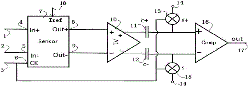
[0019] Below with the accompanying drawings ( figure 1 ) to illustrate the present invention.

[0020] figure 1 It is a schematic diagram of the structure and principle of the self-calibration current comparison circuit implementing the present invention. Such as figure 1 As shown, the self-calibration current comparison circuit includes a current sensor 7 , an amplifier 10 , a self-calibration threshold storage circuit and a comparator 16 connected in sequence, and the output terminal of the comparator 16 is connected to the system output terminal 17 . The current sensor 7 has a measured current input terminal 4 (for connecting the external measured current input line 1), a measured current output terminal 5 (for connecting the external measured current output line 2) and a sensor clock terminal 6 (for connecting the external measured current output line 2). For connecting the external clock circuit connection line 3), the self-calibration threshold storage circuit include...


PUM


Abstract

The invention provides a self-calibration current comparator circuit. The automatic elimination of possible comparator input offset and the error change generated by a current sensor in an operation is facilitated, and thus better detection precision and precise current measurement are realized well. Based on the self-calibration function of the invention, an MOS tube in a measured current path is fully utilized, with an MOS tube switch-on resistor as the current sensor, a smaller PCB area and high integration are realized. The self-calibration current comparator circuit is characterized in that the self-calibration current comparator circuit comprises the current sensor, an amplifier, a self-calibration threshold memory circuit and a comparator connected in order, and the output end of the comparator is connected to a system output end.

Description

technical field [0001] The invention relates to a precision current comparison circuit, especially a self-calibration current comparison circuit, which is beneficial to automatically eliminate possible comparator input offsets and error changes generated by current sensors during operation, thereby achieving better detection accuracy and precise current measurement . Based on the self-calibration function of the present invention, it is beneficial to make full use of the MOS tube on the measured current path, and use the on-resistance of the MOS tube as a current sensor, thereby realizing smaller PCB area and higher integration. Background technique [0002] Current comparator circuits are widely used in overcurrent detection of loads. In many applications, current overcurrent detection is a key link in system safety protection. Because the current is not easy to compare directly, the usual practice is to convert the current into a voltage through a sensor (current sensor)...

Claims


Application Information

Patent Timeline
Patent Type & Authority Applications(China)
IPC IPC(8): G01R19/165G01R35/00
CPCG01R19/165G01R35/005
Inventor 林毅竟满雪城
Owner SG MICRO
Why Eureka
Try Eureka