Precise high-voltage current mutual inductor and error testing system and method thereof

A high-voltage current and transformer technology, applied in voltage/current isolation, instruments, measuring devices, etc., can solve the problem of inability to directly measure the error of high-voltage current transformers, and achieve the effect of eliminating error changes and ensuring accuracy

Active Publication Date: 2015-02-04
STATE GRID CORP OF CHINA +1
View PDF5 Cites 9 Cited by
  • Summary
  • Abstract
  • Description
  • Claims
  • Application Information

AI Technical Summary

Problems solved by technology

[0003] At present, the verification of high-voltage current transformers in the power system is carried out under low-voltage conditions according to the JJG 1021-2007 "Power Transformer" regulations, although the JJG 1021-2007 "Power Transform

Method used


Image

  • Precise high-voltage current mutual inductor and error testing system and method thereof
  • Precise high-voltage current mutual inductor and error testing system and method thereof
  • Precise high-voltage current mutual inductor and error testing system and method thereof

Examples


Example Embodiment

[0029] The present invention will be further described in detail below in conjunction with the drawings and specific embodiments:

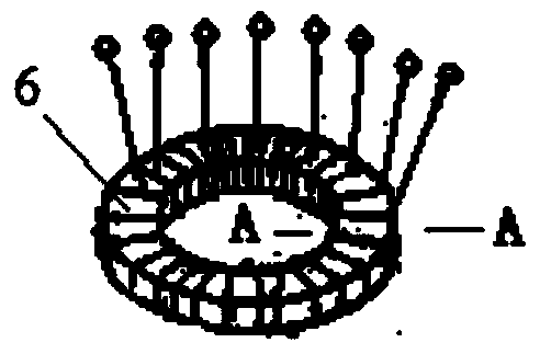
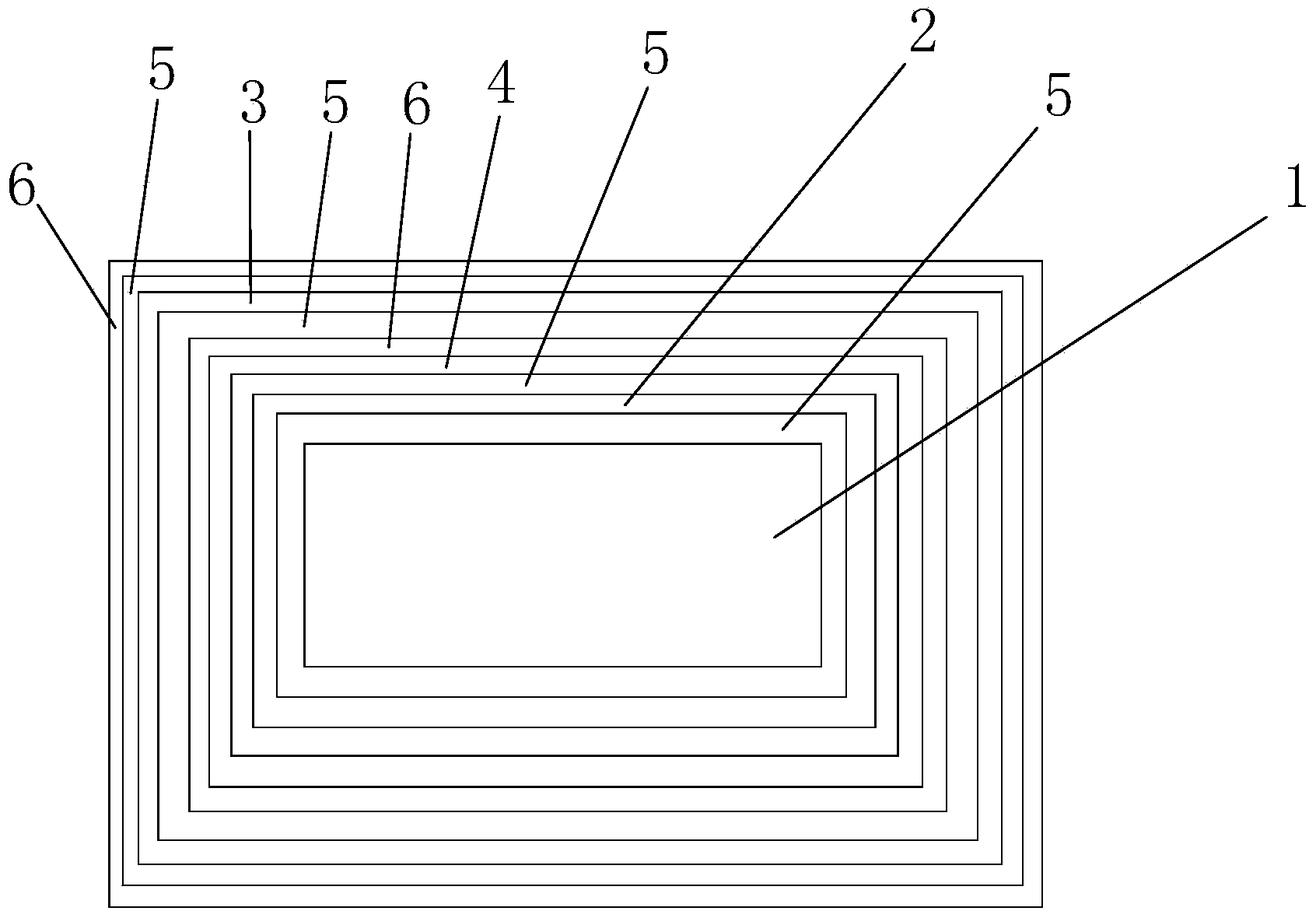
[0030] Such as Figure 1~3 The precision high voltage current transformer shown includes an iron core 1, a multi-winding and multi-tap compensation coil 2, a multi-winding and multi-tap primary coil 3, a multi-winding and multi-tap secondary coil 4, an insulating layer 5 and a shielding layer 6, Wherein, a multi-winding and multi-tap compensation coil 2 is arranged on the outer layer of the iron core 1, and a first insulating layer 5 is provided between the multi-winding and multi-tap compensation coil 2 and the outer layer of the iron core 1;

[0031] The outer layer of the multi-winding and multi-tap compensation coil 2 is wound with a multi-winding and multi-tap secondary coil 4, and a second insulating layer 5 is provided between the multi-winding and multi-tap compensation coil 2 and the multi-winding and multi-tap secondary coil 4 ;

[0032] The ...


PUM


Abstract

The invention discloses a precise high-voltage current mutual inductor. A multi-winding multi-tap compensating coil winds an outer layer of an iron core; a first insulating layer is arranged between the multi-winding multi-tap compensating coil and the outer layer of the iron core; a multi-winding multi-tap secondary coil winds the outer layer of the multi-winding multi-tap compensating coil; a second insulating layer is arranged between the multi-winding multi-tap compensating coil and the multi-winding multi-tap secondary coil; a multi-winding multi-tap primary coil winds the exterior of the multi-winding multi-tap secondary coil; a first shielding layer and a third insulating layer are arranged between the multi-winding multi-tap secondary coil and the multi-winding multi-tap primary coil; the second shielding layer winds the exterior of the multi-winding multi-tap primary coil; a fourth insulating layer is arranged between the multi-winding multi-tap primary coil and the second shielding layer; the first shielding layer and the second shielding layer are provided with extension lines. The precise high-voltage current mutual inductor can directly and accurately measure the error of a high-voltage current mutual inductor under actual high-voltage environment.

Description

technical field [0001] The invention relates to the technical field of electric energy measurement, in particular to a precision high-voltage current transformer and an error testing system and method for the transformer. Background technique [0002] In the power system, the current transformer is widely used as a primary component in practical applications. It changes the large current in the primary system into a small current suitable for measurement and protection according to the transformation ratio. The rated secondary current is usually 5A or 1A. . Due to the independent accounting of power plants and power grids (transmission and transformation systems), the accuracy of energy metering at gateways is particularly important. As one of the important components of primary equipment, current transformers are directly related to the accuracy and rationality of the converted data. The calculation of the error is related to the economic interests of the power plant, the ...

Claims


Application Information

Patent Timeline
IPC IPC(8): G01R35/02G01R15/18
Inventor 吴宏斌史会轩张旭飞魏华李原王龙华李映辉吴巍邓德勇乐文静
Owner STATE GRID CORP OF CHINA
Why Eureka
Try Eureka