A hand dryer device

A hand dryer and sliding connection technology, which is applied in the field of hand dryers, can solve the problems of increased difficulty in installation or maintenance, cumbersome disassembly steps, and unreliable fixation, and achieve the effects of simple structure, improved safety, and convenient installation

Active Publication Date: 2017-11-24
连云港市赣榆区综合检验检测中心
View PDF12 Cites 0 Cited by
  • Summary
  • Abstract
  • Description
  • Claims
  • Application Information

AI Technical Summary

Problems solved by technology

[0002] Hand dryers used to dehumidify hands can often be seen in the bathrooms of some shopping malls or hotels. The hand dryers in the prior art are generally fixed on the wall by buckle structure or screw fastening. It is electrically connected to the power supply part in the wall to realize the power supply work. However, it is fixed by a buckle structure, although it is convenient, but the fixation is not firm and there is a danger of falling. Although it is fixed by screws, the disassembly steps are relatively cumbersome. , which increases the difficulty of installation or inspection and maintenance. At the same time, during inspection and maintenance, since there is no protective structure between the hand dryer and the power supply part in the wall, it is very easy to touch the conductive parts in the power supply part and cause an electric shock risk, there is a greater security risk

Method used


Image

  • A hand dryer device
  • A hand dryer device
  • A hand dryer device

Examples


Embodiment Construction

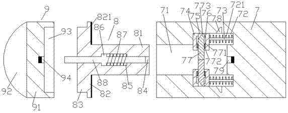
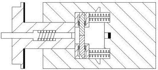
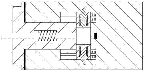
[0020] Such as Figure 1-Figure 6 As shown, a hand dryer device of the present invention includes a base 7, a rotating part 8 and an assembly part 9. The inside of the base 7 on the left side is provided with an inner threaded groove 71, and the inner The upper and lower inner walls on the right side of the helical thread empty groove 71 are correspondingly provided with a sliding connection groove 72, and the side of the sliding connection groove 72 away from the inner helical thread empty groove 71 is provided with a beveled groove 78, and each of the sliding joints Sliding joint rods 73 are provided in the grooves 72, and a sliding joint block 74 is slidingly connected to the sliding joint rods 73, and the sliding joint block 74 is slidingly engaged with the sliding joint groove 72, and the sliding joint block The outer side of the sliding joint rod 73 on the right side of 74 is wound with a first elastic member 721, and the side of the sliding joint block 74 close to the i...


PUM


Abstract

The invention discloses a hand drying device. The device comprises a base, a spinning part and an assembly part, wherein an inner spiral grained empty groove is formed inside the base close to the left side, and sliding grooves are correspondingly formed in upper and lower inner walls of the inner spiral grained empty groove, close to the right side; a beveling groove is formed in one side, away from the inner spiral grained empty groove, of each sliding groove; a sliding rod is arranged in each sliding groove and is connected with a sliding block in a sliding fit manner, each sliding block and the corresponding sliding groove are in sliding fit, a first elastic part is wound outside each sliding rod on the right side of the corresponding sliding block, one side, close to the inner spiral grained empty groove, of the sliding block runs into the inner spiral grained empty groove; a first hole slot is formed in each sliding block in a penetrating manner, and a first square groove is formed in the middle end inside each first hole slot; and a first flange part is arranged in each first square groove in a sliding manner, and a stop dog is connected in each first hole slot in a sliding manner. The hand drying device has the advantages of simple structure, convenience in assembly and high stability, has an electric shock protection function, and can be used for improving the safety during maintenance.

Description

technical field [0001] The invention relates to the technical field of hand dryers, in particular to a hand dryer device. Background technique [0002] Hand dryers used to dehumidify hands can often be seen in the bathrooms of some shopping malls or hotels. The hand dryers in the prior art are generally fixed on the wall by buckle structure or screw fastening. It is electrically connected to the power supply part in the wall to realize the power supply work. However, it is fixed by a buckle structure, although it is convenient, but the fixation is not firm and there is a danger of falling. Although it is fixed by screws, the disassembly steps are relatively cumbersome. , which increases the difficulty of installation or inspection and maintenance. At the same time, during inspection and maintenance, since there is no protective structure between the hand dryer and the power supply part in the wall, it is very easy to touch the conductive parts in the power supply part and ca...

Claims


Application Information

Patent Timeline
Patent Type & Authority Patents(China)
IPC IPC(8): A47K10/48
CPCA47K10/48
Inventor 王爱实陈磊
Owner 连云港市赣榆区综合检验检测中心
Why Eureka
Try Eureka