Waste heat removal system and method and nuclear power system

A technology of waste heat discharge system and coolant system, applied in the field of nuclear power system, can solve the problems of complex device and poor reliability, etc.

Pending Publication Date: 2021-11-12
CHINA NUCLEAR POWER ENG CO LTD
View PDF0 Cites 0 Cited by
  • Summary
  • Abstract
  • Description
  • Claims
  • Application Information

AI Technical Summary

Problems solved by technology

However, it needs related instrument control logic measures to realize, the device is complicated and the reliability is poor

Method used


Image

  • Waste heat removal system and method and nuclear power system
  • Waste heat removal system and method and nuclear power system
  • Waste heat removal system and method and nuclear power system

Examples


Embodiment 1

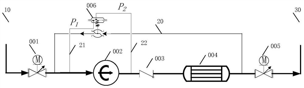
[0051] Such as figure 1 As shown, this embodiment provides a waste heat removal system, including: a main pipe, a small flow pipe 20, a pressure taking pipe 21 before the pump, and a pressure taking pipe 22 after the pump,

[0052] The main pipe is connected between the hot section 10 and the cold section 30 of the reactor coolant system loop, and along the coolant flow direction from the hot section 10 to the cold section 30, the main pipe is provided with a first isolation valve 001, a circulation pump 002, a heat exchange device 004 and second isolation valve 005,

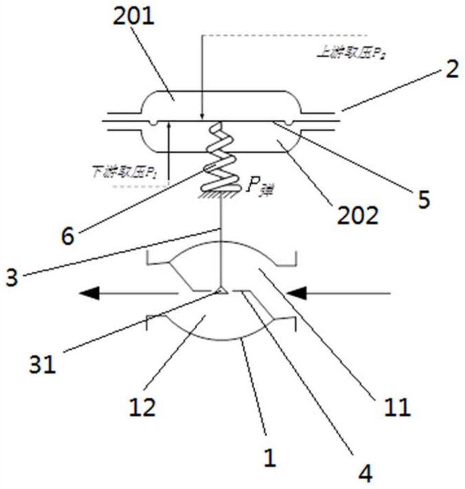
[0053] The small flow pipe 20 is connected between the first communication port of the main pipe and the second communication port. The first communication port is between the first isolation valve 001 and the circulation pump 002. The position between the two isolation valves 005, the small flow pipe 20 is provided with a self-operated differential pressure regulating valve 006,

[0054] The circulating pump ...

Embodiment 2

[0080] This embodiment provides a method for utilizing the system of Embodiment 1 to discharge waste heat in the reactor coolant system, comprising the following steps:

[0081] Open the first isolation valve 001, close the second isolation valve 005, so that the main pipe communicates with the small flow pipe 20, start the circulation pump 002, and use the power of the circulation pump 002 to transfer the coolant in the circulation formed by the small flow pipe 20 and the main pipe. heating to the set value,

[0082] Open the second isolation valve 005 to disconnect the main pipe from the small flow pipe 20, and form a circulation with the reactor coolant system, and pump the coolant in the hot section 10 of the loop of the reactor coolant system through the power of the circulation pump 002 After being cooled in the heat exchanger 004, it is sent to the hot section 10 of the reactor coolant system loop.

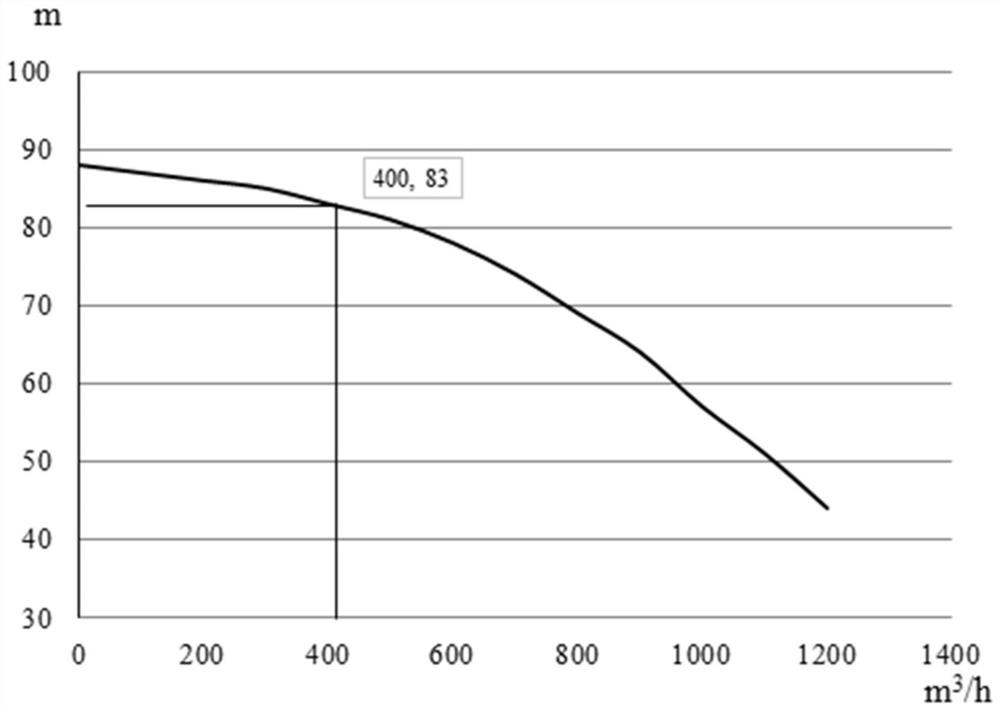
[0083] Taking the waste heat discharge system adopted in a certain po...

Embodiment 3

[0085] This embodiment provides a nuclear power system, including a reactor coolant system and the waste heat removal system of Embodiment 1.


PUM


Abstract

The invention provides a waste heat removal system and method and a nuclear power system. The waste heat removal system is characterized in that a main pipe is connected between a hot section and a cold section of a reactor coolant system, a small-flow pipe is connected between two communicating ports of the main pipe, a self-operated pressure difference regulating valve is arranged on the small-flow pipe, a before-pump pressure tapping pipe is arranged between the front section of a main pipe pump and the regulating valve, an after-pump pressure tapping pipe is arranged between the rear section of the main pipe pump and the regulating valve, when the before-pump isolating valve on the main pipe is opened and the after-pump isolating valve is closed, or the pressure of a coolant in the cold section is increased, the pressure difference of the regulating valve is greater than a set value, so that the regulating valve is automatically opened, and communication between the small-flow pipe and the main pipe is achieved; and when the before-pump and after-pump isolating valves on the main pipe are both opened, the pressure difference of the regulating valve is less than the set value, so that the regulating valve is closed, and the small-flow pipe is disconnected from the main pipe. Therefore, the system can realize automatic opening and closing of the small-flow pipeline under different required working conditions on the premise of not needing additional instrument control logic configuration, so that the system has the advantages of simple structure and high reliability.

Description

technical field [0001] The invention specifically relates to a waste heat discharge system and method, and a nuclear power system. Background technique [0002] At present, most of the second-generation nuclear power plants operating widely in China are reactor types that continue the French pressurized water reactor nuclear power technology. The residual heat removal system is equipped with small flow pipelines, and there are no measuring devices or other valves on the pipelines. Its small flow pipeline is used to realize the preheating of the waste heat removal system, and to protect the pump when the return pipeline valve is closed and the return pipeline pressure suddenly rises, etc. When the waste heat removal system cools down the reactor, the small flow pipeline always has medium circulating. This phenomenon leads to the loss of part of the circulating cooling flow, which further leads to the reduction of the cooling capacity of the system and the deterioration of th...

Claims


Application Information

Patent Timeline
Patent Type & Authority Applications(China)
IPC IPC(8): G21C15/18G21C15/14F04B53/10F04B51/00F04B49/22F04B53/16
CPCG21C15/182G21C15/14F04B53/10F04B51/00F04B49/22F04B53/16Y02E30/30
Inventor 皮月侯婷姚亦珺李博
Owner CHINA NUCLEAR POWER ENG CO LTD
Why Eureka
Try Eureka