Expandable impeller pump

a technology of expanding impellers and impellers, which is applied in the direction of liquid fuel engines, vessel construction, marine propulsion, etc., can solve the problem of only achieving optimal design configuration of blades, and achieve the effect of facilitating compression and reducing flow vortices

Active Publication Date: 2006-03-23
PENN STATE RES FOUND +2
View PDF24 Cites 202 Cited by
  • Summary
  • Abstract
  • Description
  • Claims
  • Application Information

AI Technical Summary

Benefits of technology

[0011] The indentation can reduce flow vortices formed as the fluid moves relative to the impeller. The indentation may also facilitate compression of the impeller into the stored configuration, for example by facilitating movement of the distal end of the blade towards the hub. A typical blade has a pressure face and a suction face, and the indentation may comprise a trench parallel and adjacent to one or both of these faces. A blade may have an airfoil cross-section, the indentation being a curved trench formed in the impeller parallel to the curved proximal end of the blade.

Problems solved by technology

For example, the optimal design configuration of the blade may only be achieved with deformation under load.

Method used


Image

  • Expandable impeller pump
  • Expandable impeller pump
  • Expandable impeller pump

Examples


Embodiment Construction

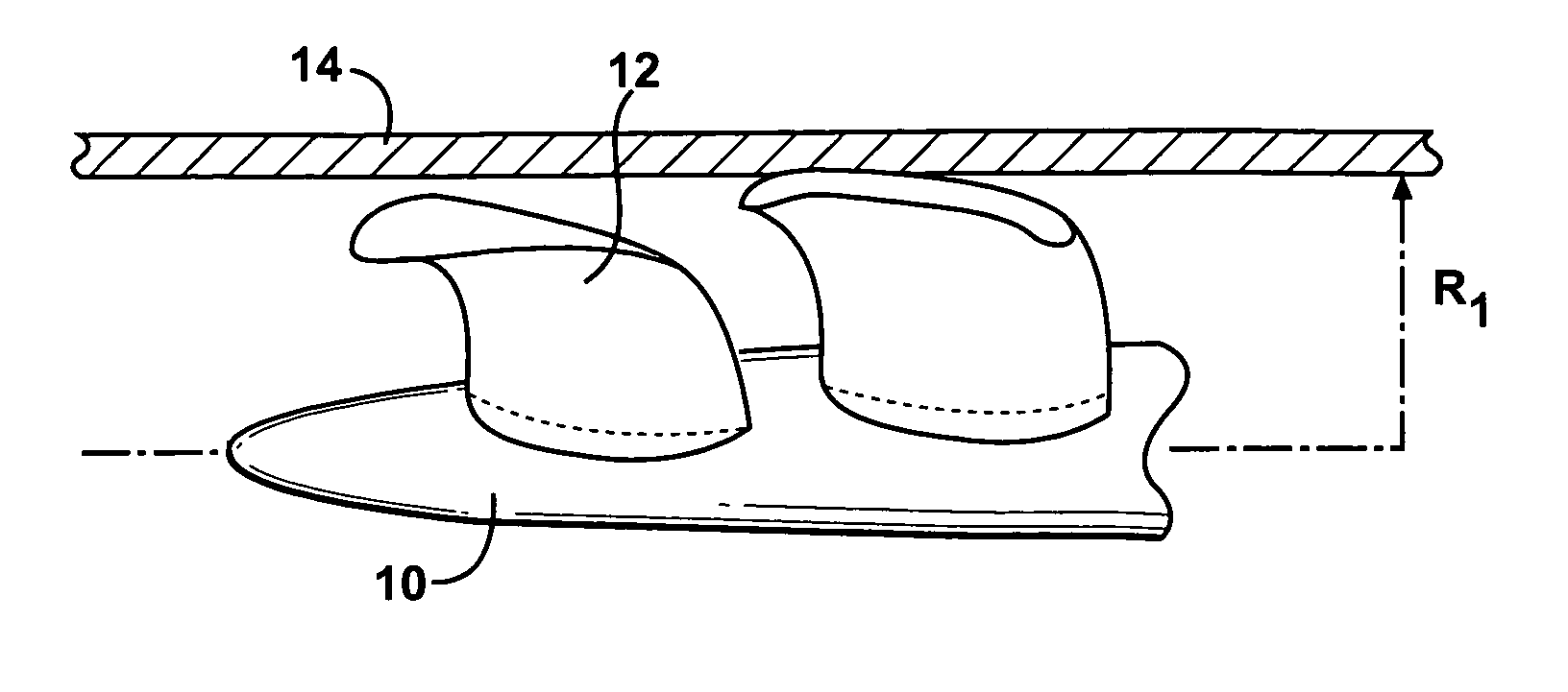
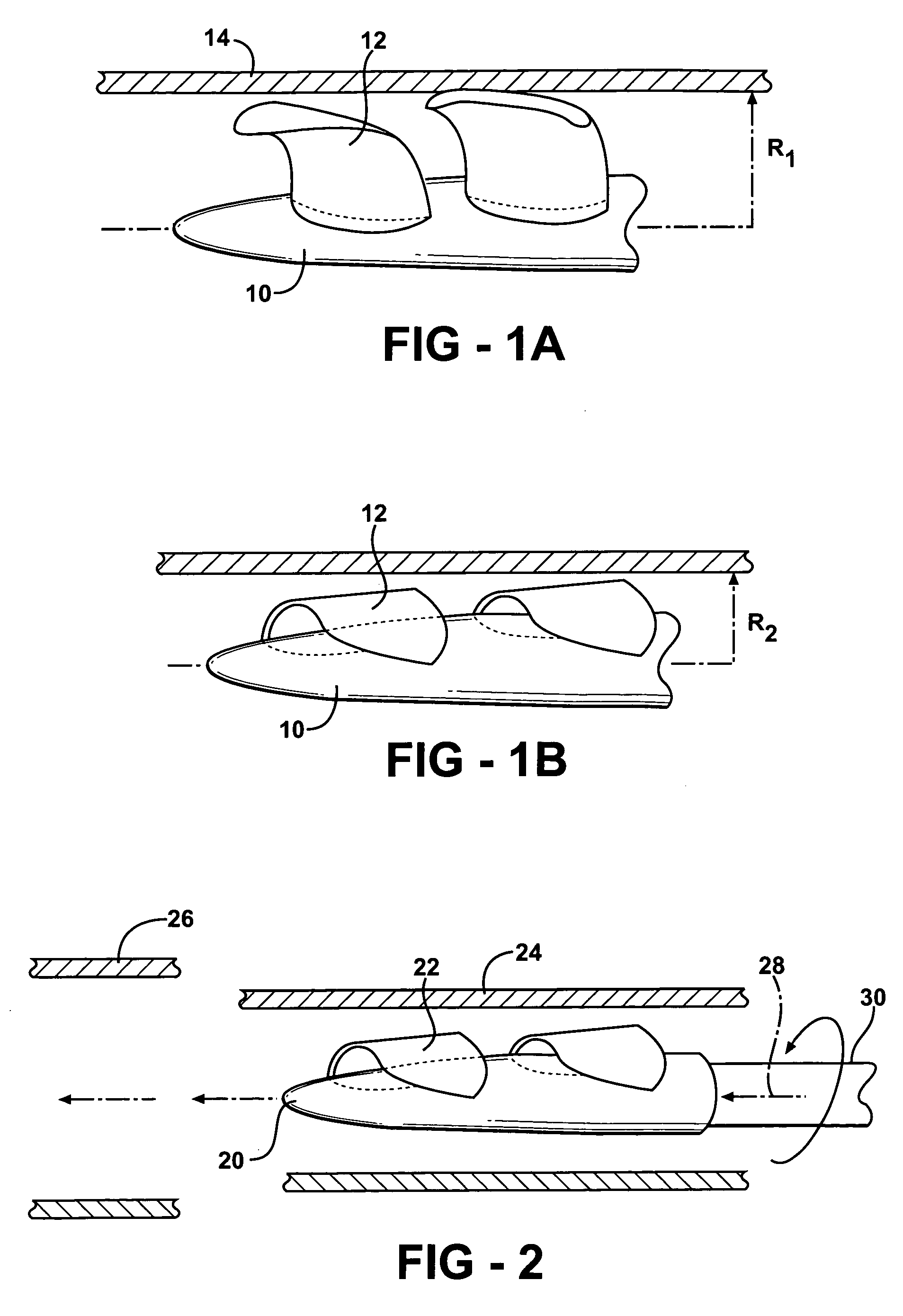
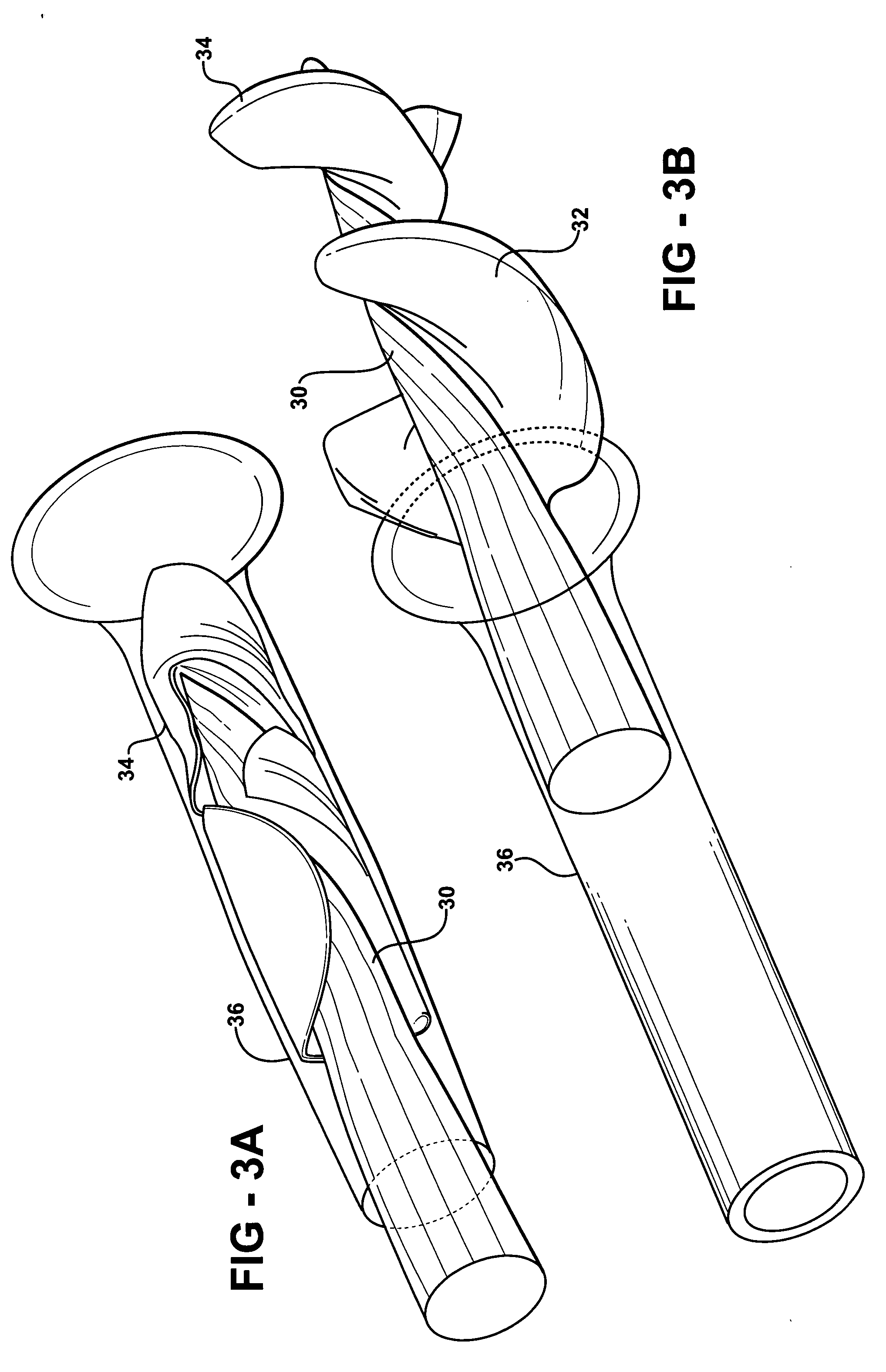
[0029] An impeller according to an embodiment of the present invention comprises a hub, and at least one blade supported by the hub. Embodiments of the present invention include impellers having at least one flexible blade, having a deployed configuration in which the blade extends away from the hub, and a stored configuration in which the impeller is radially compressed. For example, the blade may be folded in towards the hub, and held there by a storage sleeve such as a metal tube or cannula. In the stored configuration, the distal end of the blade is closer to the hub than in the deployed configuration, and the radius can be significantly less, such as less than half that of the radius in the deployed state. The sleeve may comprise a non-expandable portion, in which the impeller is stored, and an expandable portion, into which the impeller can be moved for deployment. The impeller deploys within the expanded portion of the sleeve.

[0030] Impellers according to the present inventi...


PUM

PropertyMeasurementUnit
flexural modulusaaaaaaaaaa
elongationaaaaaaaaaa
diameteraaaaaaaaaa

Abstract

An impeller according to an example of the present invention comprises a hub, and at least one blade supported by the hub. The impeller has a deployed configuration in which the blade extends away from the hub, and a stored configuration in which the impeller is radially compressed, for example by folding the blade towards the hub. The impeller may comprise a plurality of blades, arranged in blade rows, to facilitate radial compression of the blades. The outer edge of a blade may have a winglet, and the base of the blade may have an associated indentation to facilitate folding of the blade.

Description

REFERENCE TO RELATED APPLICATION [0001] This application claims priority of U.S. Provisional Patent Application Ser. No. 60 / 610,938, filed Sep. 17, 2004, the entire content of which is incorporated herein by reference.FIELD OF THE INVENTION [0002] The present invention relates to fluid pumping impellers, in particular to expandable impellers. BACKGROUND OF THE INVENTION [0003] Conventional impellers are manufactured with a particular blade configuration, and significant deformation of the blades is generally undesirable. Conventionally, the impeller has the same configuration during storage, movement to its operating location, and use. However, there are situations where access to the operating location is through a restricted space, or space is otherwise at a premium during storage or transport of the impeller, in which case the use of conventional impellers can be problematic. SUMMARY OF THE INVENTION [0004] An impeller according to an embodiment of the present invention comprises...

Claims


Application Information

Patent Timeline
Patent Type & Authority Applications(United States)
IPC IPC(8): B64C11/28A61M60/135A61M60/237A61M60/414A61M60/808
CPCA61M1/101B63B2231/42B63H1/26B63H11/08F04D29/026F04D29/181Y10T29/49229F04D29/382F04D3/00Y10S415/90A61M1/1024A61M1/125F04D29/247F05D2300/43A61M60/414A61M60/148A61M60/808A61M60/237F03G7/0614F04D29/528F05D2210/11F05D2250/52F05D2250/51F05D2240/305F05D2240/306A61M60/135A61M60/205F04D3/02F04D19/02F04D29/526
Inventor MCBRIDE, MARK W.MALLISON, THOMAS M.DILLON, GREGORYCAMPBELL, ROBERT L.BOGER, DAVID
Owner PENN STATE RES FOUND
Why Eureka
Try Eureka