Implantable intraluminal device and method of using same in treating aneurysms

a technology of intraluminal device and aneurysm, which is applied in the field of intraluminal device, can solve the problems of inability to achieve the effect of unable to meet the needs of patients, so as to achieve the effect of maintaining patency in the perforating and/or branch vessels and reducing the blood flow to the aneurysm

Inactive Publication Date: 2003-05-29
STRYKER CORP
View PDF0 Cites 193 Cited by
  • Summary
  • Abstract
  • Description
  • Claims
  • Application Information

AI Technical Summary

Benefits of technology

0023] An object of the present invention is to provide an intraluminal device having advantages in one or more of the above respects for implantation in a blood vessel having an aneurysm in order to treat the aneurysm. Another object of the invention is to provide such an intraluminal device particularly useful for implantation in a blood vessel having an aneurysms at or proximate to one or more perforating vessels and / or a bifurcation leading to a branch vessel such as to reduce the blood flow to the aneurysms while still maintaining patency in the perforating and / or branch vessels.

Problems solved by technology

Because of the high mortality and morbidity rates, and because the condition of many patients does not permit them to undergo an open operation, the surgical procedure is often delayed or not practical.
Widespread, long-term experience with this technique has shown several risks and limitations.
The relatively low success rate is due to technical limitations (e.g., coil flexibility, shape, and dimensions) which prevent tight packing of the sac of the aneurysm, especially aneurysms with wide necks [3].
Other difficulties are associated with the presence of preexisting thrombus within the aneurysm cavity, which may be sheared off into the parent trunk leading to parent artery occlusion.
Also aneurysm perforation may occur during placement of coils into the aneurysm.
Additionally, occurrence of coil movement and compaction may foster aneurysm revascularization or growth.
One of the disadvantages of this method is that detachable balloons, when inflated, typically do not conform to the interior configuration of the aneurysm sac.
Thus, there is an increased risk that the detachable balloon will rupture the sac of the aneurysm.
The use of this technology has been limited until recently by the lack of available stents and stent delivery systems capable of safe and effective navigation through the intercranial vessels.
The use of such stents is particularly difficult with respect to aneurysms in head blood vessels because of the number of perforating vessels in such blood vessels, and thereby the increased danger that one or more perforating vessels may be in the vicinity of such an aneurysm.
Thus, there is a serious danger that the placement of a conventional endovascular stent within the parent artery across the aneurysm neck to reduce blood flow to the aneurysm, to promote intra-aneurysm stasis and thrombosis [4,5].
Technically it is very difficult to produce and accurately deploy the stents described in the above McCrory, Brown et al and Wallsten patents for treating aneurysms by using presently available delivery systems.
The difficulties include not only in producing such stents of different permeabilities, but also in deploying them such that the portion of low permeability is exactly aligned with the aneurysm neck.
Additionally, particularly in tortuous, ectatic vessels, existing stiff stents are difficult to introduce and may results in kinking such as to cause the failure of the deployment process.

Method used


Image

  • Implantable intraluminal device and method of using same in treating aneurysms
  • Implantable intraluminal device and method of using same in treating aneurysms
  • Implantable intraluminal device and method of using same in treating aneurysms

Examples


example 1

[0068] Given:

[0069] 1. Artery diameter=3 mm

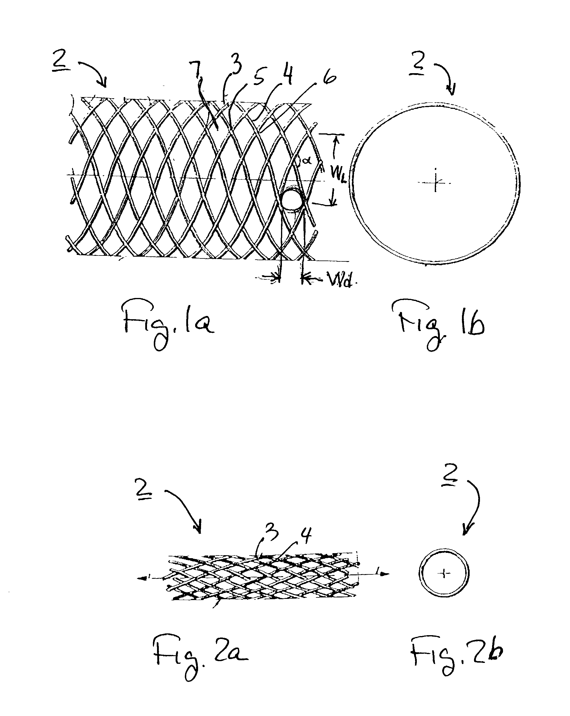
[0070] 2. Braiding angle .alpha.=90.degree.

[0071] A porosity index of 70% can achieved by changing the filament diameter and the number of filaments as follows:

1 Windows Artery Braiding Number Filaments Inscribed Porosity Diameter Angle of Fil- Width Diameter Index # [mm] [deg] aments [.mu.m] [.mu.m] [%] 1(a) 3 90 108 20 100 70 1(b) 3 90 78 27 140 70 1(c) 3 90 62 35 180 70 Note: For round cross-section filaments, the bending stiffness of #1(a) in its contracted condition is one-fifth that of #1(c) due to the smaller diameter filaments in #1(a).

example 2

[0072] Given:

[0073] 1. Artery diameter=3 mm

[0074] 2. Braiding angle .alpha.=90.degree.

[0075] 3. Filaments diameter=27 .mu.m

[0076] The porosity index can changes by changing the number of filaments as follows:

2 Windows Artery Braiding Number Filament Inscribed Porosity Diameter Angle of Fil- Diameter Diameter Index # [mm] [deg] aments [.mu.m] [.mu.m] [%] 2(a) 3 90 64 27 180 75 2(b) 3 90 108 27 140 70 2(c) 3 90 110 27 80 60 Note: For round cross-section filaments, the bending stiffness of #2(a) in its contracted condition is 60% of #2(c) due to the smaller number of filaments in #2(a).

example 3

[0077] Given:

[0078] 1. Artery diameter=3 mm

[0079] 2. Number of filaments=78

[0080] 3. Filaments diameter=27 .mu.m

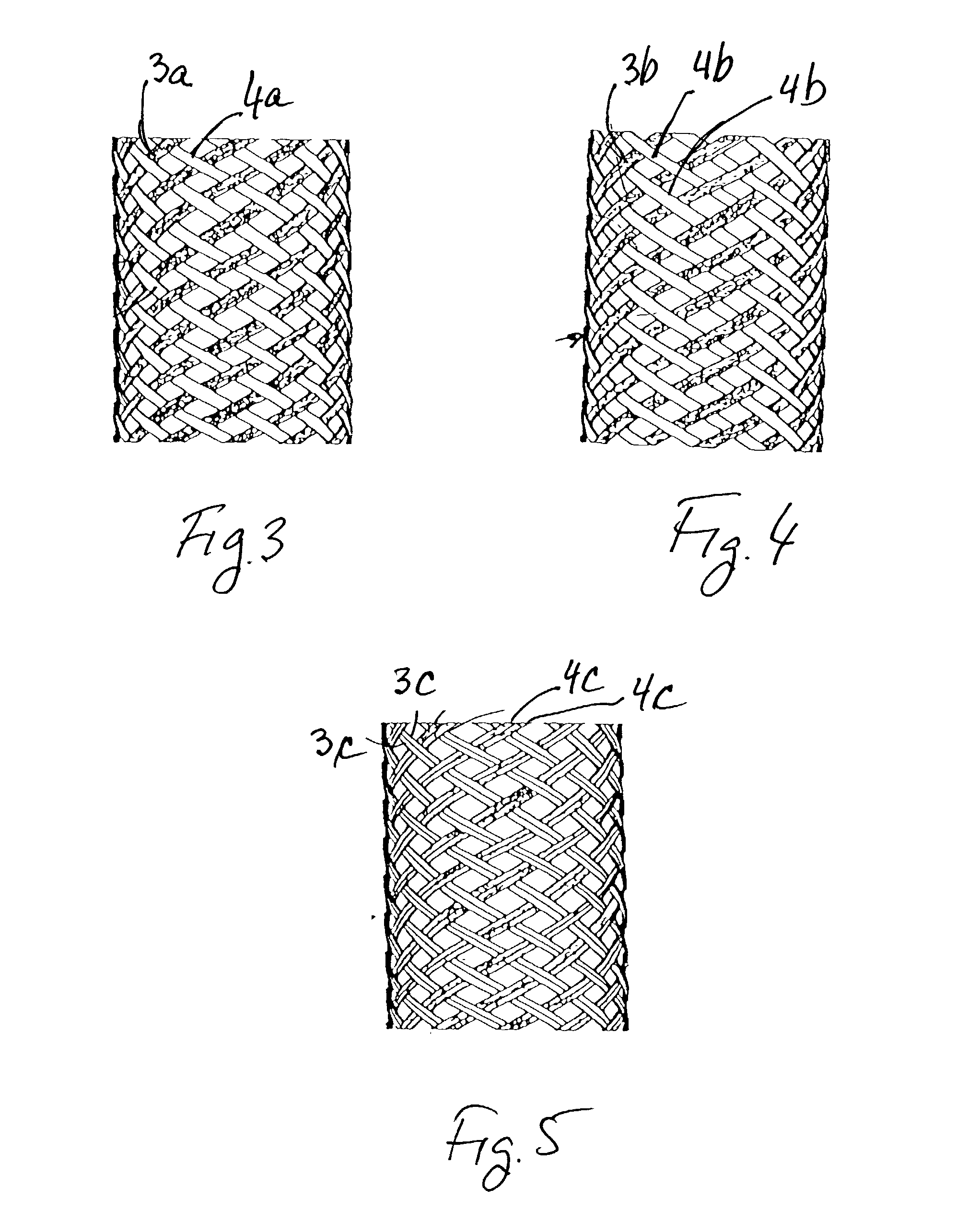
[0081] The porosity index can reduced from its maximum value at .alpha.=90.degree. in # 3(a) by changing, i.e., increasing in # 3(b) or decreasing in # 3(c) the braiding angle .alpha. as follows:

3 Windows Artery Braiding Number Filament Inscribed Porosity Diameter Angle of Fil- diameter Diameter Index # [mm] [deg] aments [.mu.m] [.mu.m] [%] 3(a) 3 90 78 27 140 70 3(b) 3 106 78 27 110 65 3(c) 3 56 78 27 110 65


PUM


Abstract

An intraluminal device implantable in a blood vessel having an aneurysm therein in the vicinity of a perforating vessel and/or of a bifurcation leading to a branch vessel. The intraluminal device includes a mesh-like tube of bio-compatible material having an expanded condition in which the tube diameter is slightly larger than the diameter of the blood vessel in which it is to be implanted, and the tube length is sufficient to straddle the aneurysm and to be anchored to the blood vessel on the opposite sides of the aneurysm. The mesh-like tube also has a contracted condition wherein it is sufficiently flexible so as to be easily manipulatable through the blood vessel to straddle the aneurysm. In its expanded condition, the mesh-like tube has a porosity index of 55%-80% such as to reduce the flow of blood through its wall to the aneurysm sufficiently to decrease the possibility of rupture of the aneurysm but not to unduly reduce the blood flow to a perforating or branch vessel to the degree likely to cause significant damage to tissues supplied with blood by such perforating or branch vessel.

Description

[0001] The present invention is related to Provisional Application No. 60 / 332,013 filed 23 Nov. 2001, the contents of which are incorporated herein by reference, and claims the priority date of that application.[0002] The present invention relates to intraluminal devices implantable in a blood vessel for the treatment of aneurysms especially brain aneurysms. The invention also relates to methods of treating aneurysms using such intraluminal devices.[0003] A number of publications as listed at the end of this specification are incorporated herein by reference in their entireties for background information and are numerically referenced in the following text:[0004] Intracranial aneurysms are the main cause of nontraumatic subarachnoid hemorrhage and are responsible for about 25% of all deaths relating to cerebrovascular events. Autopsy studies show that the overall frequency of intracranial aneurysms in the general population is approximately 5 percent and suggest that 10 to 15 millio...

Claims


Application Information

Patent Timeline
Patent Type & Authority Applications(United States)
IPC IPC(8): A61F2/06A61F2/82A61F2/90
CPCA61F2/07A61F2/82A61F2/90A61F2002/065Y10S623/909A61F2002/821A61F2002/823A61F2250/0023A61F2002/068
Inventor YODFAT, OFERLIEBER, BARUCHGRAD, YGAELNISHRI, BOAZ
Owner STRYKER CORP
Why Eureka
Try Eureka