Method for performing welding in wire wound potentiometer

A welding method and potentiometer technology, applied in welding equipment, metal processing equipment, manufacturing tools, etc., can solve the problems of difficult welding of microelectronic devices, and achieve the effect of improving stability, improving production efficiency, and realizing semi-automation.

Active Publication Date: 2017-05-31
WUHAN UNIV OF TECH +1
View PDF4 Cites 0 Cited by
  • Summary
  • Abstract
  • Description
  • Claims
  • Application Information

AI Technical Summary

Problems solved by technology

[0004] The purpose of the present invention is to design a new welding process for microelectronic devices, so as to solve the technical difficulty of welding the small area inside the microelectronic devices.

Method used


Image

  • Method for performing welding in wire wound potentiometer

Examples


Embodiment Construction

[0020] specific implementation plan

[0021] The present invention will be further described in detail below through specific embodiments in conjunction with the accompanying drawings.

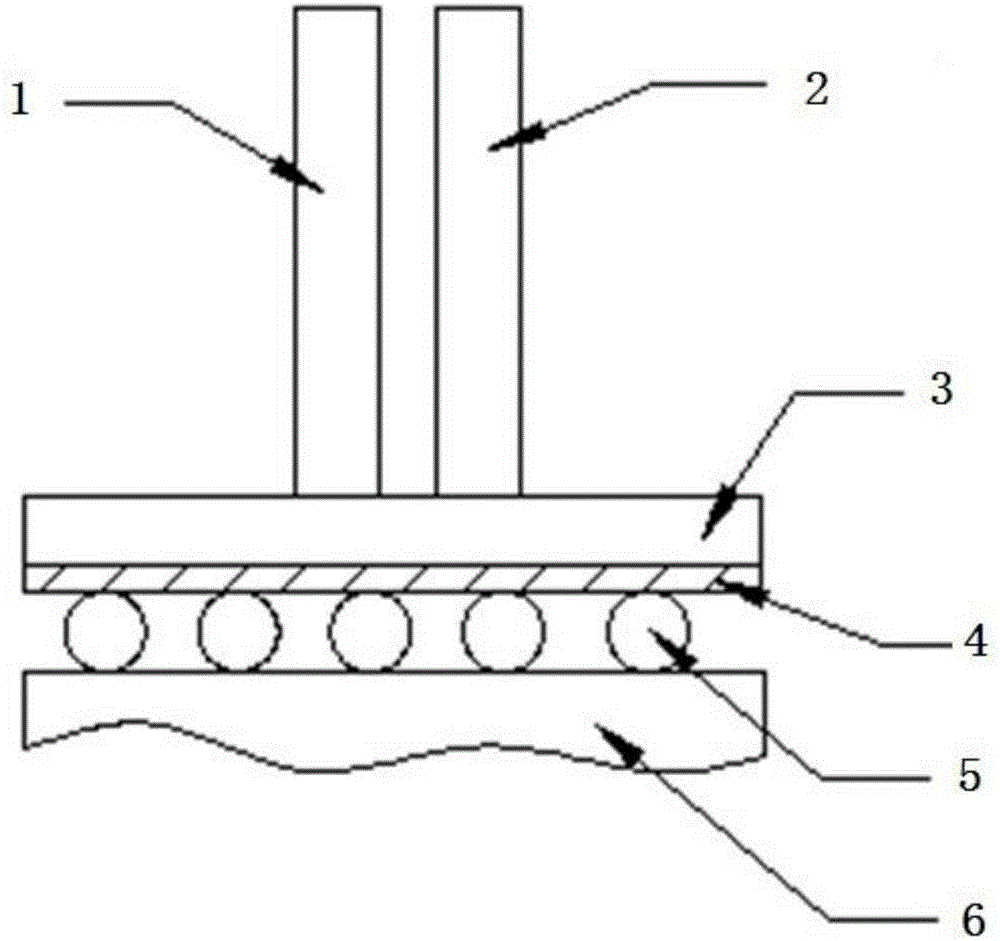
[0022] The lead-out method of the wire-wound potentiometer of the present invention is to utilize the high-temperature brazing of the resistance wire and the electrode sheet. The resistance wire is wound on the copper core coated with an insulating layer, and the electrode sheet can be directly connected to an external circuit, which simplifies the lead-out method. The main difficulties in welding the electrode sheet and the resistance wire are: the welding area is small, about 0.6mm*0.8mm, and the ordinary tin-plated solder method cannot be used to obtain a joint with excellent performance; the resistance wire is easy to break, and a single When the electrodes are welded on both sides, it is easy to damage the resistance wire or even damage the insulation layer on the copper core, resulting i...


PUM


Abstract

The invention discloses a method for performing high-pressure brazing on a resistance wire and an electrode in a wire wound potentiometer, and relates to new welding technology of microelectronic devices. The method comprises the following steps of: firstly, preparing materials to be welded, including an electrode slice of which the surface to be welded is smaller than 1mm*1mm, solid brazing filler slices in the same size, scaling powder, and the resistance wire wound on a copper core coated with an insulating layer; welding the solid brazing filler slice with the same area as the electrode slice on the surface to be welded, of the electrode slice; uniformly coating the scaling powder on the surface of the brazing filler slice on the electrode slice; finally, placing the electrode slice and the potentiometer in a positioning fixture; and welding the electrode and the resistance wire together by utilizing resistance brazing controlled by a computer program. Through the adoption of the welding method disclosed by the invention, the electrode and the resistance wire can be firmly welded, and besides, the structure of the potentiometer can be prevented from being damaged; and the method has the advantages that operation is simple, processing is convenient, properties of a joint meet usage requirements, and the production efficiency and the stability of products can be greatly improved.

Description

technical field [0001] The invention relates to the technical field of microelectronic welding, in particular to a high-temperature brazing method for a resistance wire and an electrode sheet in a wire-wound potentiometer. Background technique [0002] In the manufacture and assembly of microelectronic devices, the quality of soldering technology is the key link to determine the final quality of products. In the manufacture of microelectronic devices, since the welding area is often relatively small, the size requirements of the device are relatively high, so the requirements for welding are also higher. Leading out a wirewound potentiometer must not only provide a good, strong electrical connection, but also not subject the potentiometer to damage or stress, either internally or externally. [0003] Commonly used lead-out methods are as follows: First, a small piece of metal is brazed on several turns of wires of the resistance element, and then the metal sheet and the ext...

Claims


Application Information

Patent Timeline
Patent Type & Authority Applications(China)
IPC IPC(8): B23K1/00
CPCB23K1/0004B23K1/0016
Inventor 滕用进盛玮东肖勇
Owner WUHAN UNIV OF TECH
Why Eureka
Try Eureka