A laser cladding head component with adjustable cladding trajectory

A technology of laser cladding and cladding head, which is applied in the direction of laser welding equipment, metal processing equipment, welding equipment, etc., can solve the problems of unstable cladding track height, cross-sectional shape, unfavorable cladding head arrangement of heat dissipation devices, etc., to achieve a solution The laser power is limited, the cladding effect is guaranteed, and the cladding quality is improved

Active Publication Date: 2018-11-13
ZHEJIANG UNIV OF TECH
View PDF6 Cites 1 Cited by
  • Summary
  • Abstract
  • Description
  • Claims
  • Application Information

AI Technical Summary

Problems solved by technology

[0004] Although the above method of the Fraunhofer Laser Institute in Germany can change the width of the cladding track by changing the spot size at different positions on the track, it does not adjust the powder delivery volume and The location of the powder delivery, which will cause fluctuations in the height of the cladding track and instability of the cross-sectional shape; in addition, because the high-power laser beam passing through the lens will cause heat accumulation on the lens, this solution uses a servo motor to drive the lens to move. Facilitates the placement of heat sinks in a small space inside the cladding head, thus limiting the power of the laser beam passing through the lens

Method used


Image

  • A laser cladding head component with adjustable cladding trajectory
  • A laser cladding head component with adjustable cladding trajectory
  • A laser cladding head component with adjustable cladding trajectory

Examples


Embodiment Construction

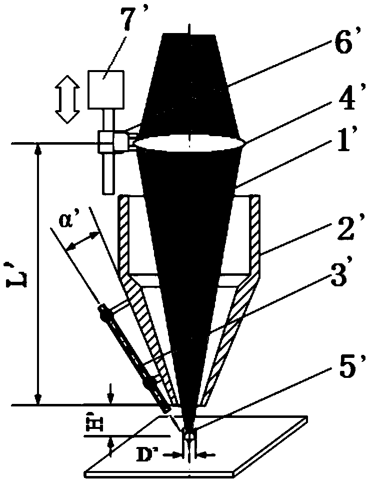
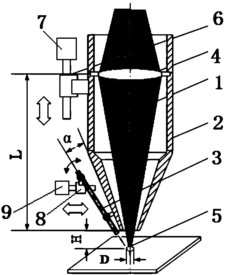
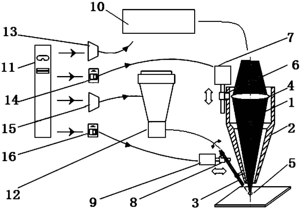
[0031] Referring to the accompanying drawings, a laser cladding head component with adjustable cladding trajectory includes a cladding head 2 installed on a vertical adjustment device that can drive the cladding head 2 to move up and down in the vertical direction , the cladding head 2 is provided with a laser entrance along the vertical direction, and the cladding head 2 is provided with a laser exit along the vertical direction; a lens 4 is provided in the cladding head 2, and the lens 4 and the The cladding head 2 is set coaxially;

[0032] The cladding head 2 is provided with a powder feeding pipe 3, and the powder feeding pipe 3 is installed on the cladding head 2 through an angle adjustment device that can adjust the angle between the powder feeding pipe 3 and the cladding head 2; The outlet of the tube 3 is downward, and the extension line of the central axis of the powder feeding tube 3 intersects the extension line of the central axis of the cladding head 2 to ensure ...


PUM


Abstract

The invention discloses a laser cladding head assembly with an adjustable cladding track. The laser cladding head assembly is characterized in that a cladding head is mounted on a vertical adjusting device which can drive the cladding head to move up and down in the vertical direction; a lens is arranged in the cladding head; the lens and the cladding head are coaxially arranged; a powder feeding pipe is mounted on the cladding head through an angle adjusting device which can adjust the included angle between the powder feeding pipe and the cladding head; an extension line of the central axis of the powder feeding pipe and an extension line of the central axis of the cladding head are intersectant; the vertical adjusting device comprises a fixedly arranged first screw rod motor; a first nut matched with a first output shaft is arranged on the outer wall of the cladding head; the first output shaft meshes with the first nut, and the cladding head is driven to move up and down; the angle adjusting device comprises a second screw rod motor and a second nut; the end, close to an outlet, of the powder feeding pipe is hinged to the outer wall of the cladding head; the end, close to an inlet, of the powder feeding pipe is hinged to the outer wall of the second nut; and the second nut meshes with a second output shaft of the second screw rod motor.

Description

technical field [0001] The invention relates to a laser cladding head component with adjustable cladding track. Background technique [0002] The coaxial cladding head is a commonly used laser cladding processing tool. The structure of the traditional coaxial cladding head is: the fixed lens group passing through the central axis converges the laser beam, and the powder feeding flow symmetrically distributed along the same central axis The laser beam and the powder flow are converged on the same axis. The laser converging point and the powder converging point of this traditional coaxial cladding head are fixed, therefore, the adjustment and change of the section width at different positions cannot be realized on one cladding track. [0003] Thin-walled complex parts such as blades have the characteristics of thin walls, complex cross-sectional tracks, and cross-sectional widths that vary with the track. When using traditional coaxial cladding heads for cladding manufacturin...

Claims


Application Information

Patent Timeline
Patent Type & Authority Patents(China)
IPC IPC(8): B23K26/342B23K26/06
CPCB23K26/06B23K26/342
Inventor 胡晓冬姚建华骆芳吴国龙董刚黄利安科瓦连柯·弗拉季米尔阿里亚肯·迈克勒如斯勒·褚克
Owner ZHEJIANG UNIV OF TECH
Why Eureka
Try Eureka