Method for Establishing a Nail Connection and a Nail for This Purpose

a technology of connecting threads and nails, which is applied in the direction of nails, bolts, fastening means, etc., can solve the problems of inability to accurately connect the thread of the screw with the hole shot into the sheet, the plurality of process steps to be executed is a disadvantage, and the connection method is not suitable for the fastening of sheets on extrusion profiles. , to achieve the effect of low jointing time, high connection quality and simple method

Active Publication Date: 2010-07-22
BOLLHOFF VERBINDUNGSTECHNIK GMBH
View PDF18 Cites 26 Cited by
  • Summary
  • Abstract
  • Description
  • Claims
  • Application Information

AI Technical Summary

Benefits of technology

[0007]The object of the present invention is to create a method for establishing a connection between two components by means of a nail driven in at a high speed and a nail for this purpose, which can be used in the case of only one-sided accessibility of the components, requires no preholing of the components, enables an extremely simple and above all quick jointing method without rotation of the nail and still leads to a high connection quality.
[0008]In the case of the method according to the invention, a nail with a nail head, a nail shank and a nail point is driven into these parts to connect two components in a joint area. For improved fastening of the components together, adhesive is applied to at least one of the components so that the adhesive is arranged between the two components. After the components have been positioned with the help of a tensioning device such that a specified gap width of a gap is set between the two components, the aforementioned nail is driven in. The nail is driven in a mainly non-rotating and axial manner into the non-preholed components in the joint area at a high speed with the help of a setting device. The step of driving in the nail is designed such that a permanent connection is established between the two components, the nail point penetrates the nail-head-side component and at least pierces the component facing away from the nail head and only one material collar is formed in the nail-head-side component, which protrudes from the nail-head-side component in the direction facing away from the nail head. Based on the method described above, the advantages of the insertion of a bolt into two components at a high speed are combined with an adhesive layer arranged between these components. The adhesive layer and the alignment of the two components or the gap between the two components is thereby selected such that the adhesive layer has an almost constant thickness despite the joint and also at least contributes to the deformation of the nail-head-side component for a stabilization of the connection between the two components. The stabilizing effect within the framework of the established connection is achieved in that during the jointing method a material collar is formed on the nail-head-side component. This material collar only protrudes from the nail-head-side component in the driving direction. Opposite the driving direction, there is no formation of a material collar or bulge, which would for example prevent the optimal fitting of the nail head on the nail-head-side component. Furthermore, the above method enables the use of nails with nail heads that do not have a ring groove that receives material on the bottom side of the nail head.
[0010]In accordance with a further preferred embodiment of the present method, the material and the geometry of the components to be fastened together and the gap width of the adhesive-containing gap between the two components is selected such that the material collar of the nail-head-side component to be designed only in the driving direction is supported on the component facing away from the nail head and bridges the gap between the nail-head-side component and the component facing away from the nail head. Further stabilization of the joint connection is thereby achieved. Moreover, in this embodiment, the self-supporting material collar also ensures the retention of the gap width with adhesive so that the adhesive between the two components is not displaced in the area adjacent to the joint area.
[0011]In accordance with a further embodiment of the present method, the adhesive is first applied in a locally restricted area to at least one of the components. Then a two-dimensional distribution of the adhesive between the nail-head-side component and the component facing away from the nail head is achieved through targeted positioning of the components using the tensioning device. This positioning distributes the adhesive amounts applied for example as a bead or bulge so that complicated adhesive layering of at least one component or adhesive distribution in a predefined layer thickness does not need to be performed. This method embodiment thus shortens the jointing method without having to accept losses in the quality of the connection.
[0015]The method according to the invention is characterized by great simplicity and extremely low jointing time, since a preholing of the components is not required and the nail is driven into and through the two components or into and at least just into the component facing away from the nail head without rotation in a single jointing process at a high speed. As confirmed in experiments, the connection between the two components established in this manner is characterized by a high connection quality. Another advantage of the method according to the invention is that two-sided accessibility of the joint area is not required when the component facing away from the nail head is sufficiently rigid.

Problems solved by technology

This jointing method is not suitable for the fastening of sheets on extrusion profiles with a closed cross-section or on internal-high-pressure-reshaped components such as required for example in vehicle construction.
In the case of this type of fastening of the two sheets together, the plurality of process steps to be executed is a disadvantage.
Furthermore, it is questionable whether the thread of the screw actually forms a reliable connection with the hole shot into the sheets.

Method used


Image

  • Method for Establishing a Nail Connection and a Nail for This Purpose
  • Method for Establishing a Nail Connection and a Nail for This Purpose
  • Method for Establishing a Nail Connection and a Nail for This Purpose

Examples


Embodiment Construction

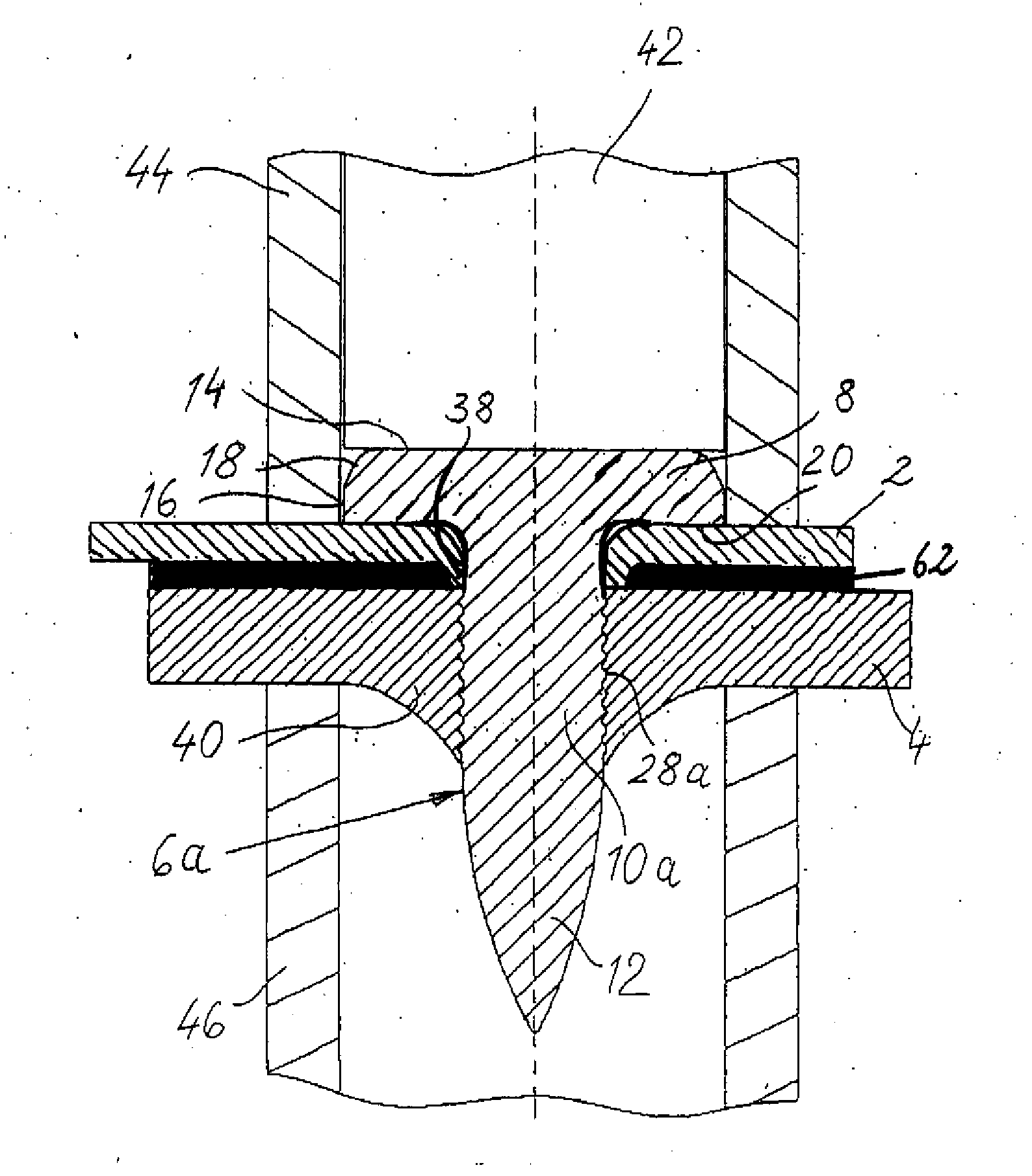
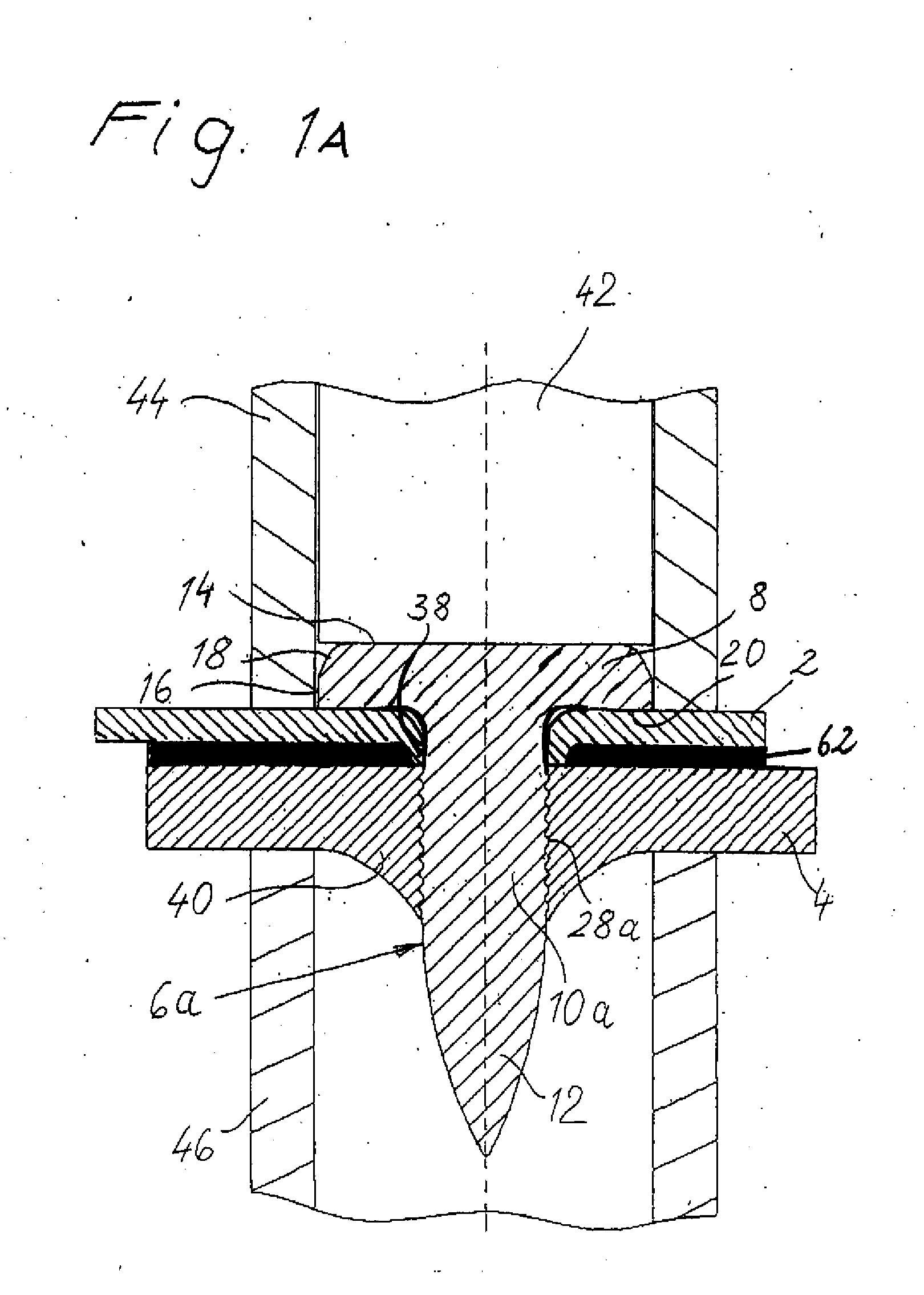
[0031]FIG. 1 shows a completed connection between a component 2 and a component 4 by means of a nail 6a. In the exemplary embodiment shown, the component 2 is a thin-walled component in the form a sheet and the component 4 is a component with a greater wall thickness, which is a profile component for example. For example, these can be body parts for vehicle construction although the invention is not limited to this.

[0032]The components 2, 4 can be made of steel, aluminum, magnesium or plastic with or without fiber content. They are not preholed before the jointing method, as will be explained in greater detail below.

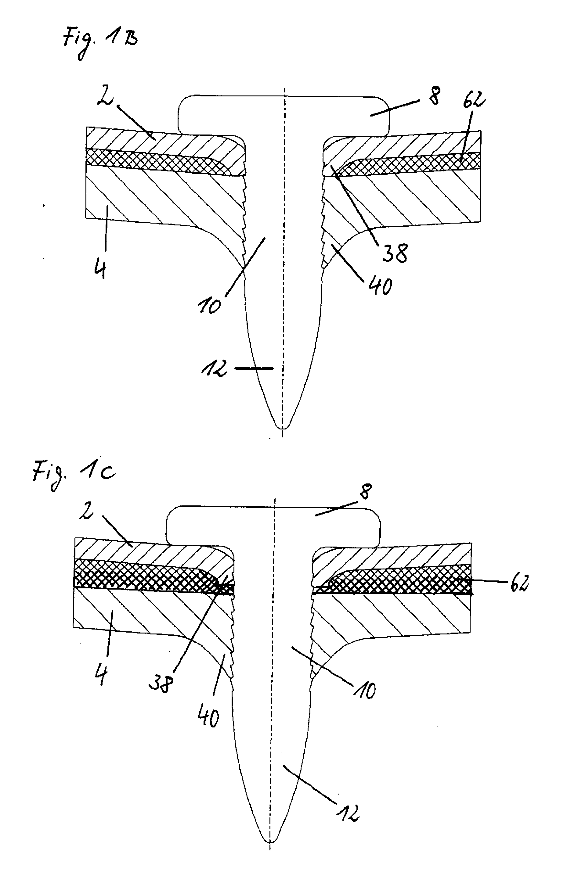
[0033]As can be seen in FIGS. 1 and 2, the nail 6a consists of a nail head 8, a nail shank 10a and a nail point 12. It is also preferred to design the nail as a functional bolt as described in DE 10 2007 017 590.8.

[0034]The nail head 8 is a flat head with an even top side 14, a cylindrical circumferential surface 16 and an even bottom side 20.

[0035]The nail shank 10a is ...


PUM

PropertyMeasurementUnit
angleaaaaaaaaaa
speedaaaaaaaaaa
speedaaaaaaaaaa

Abstract

A method for establishing a nail connection between two components and a nail for this purpose are described. The nail 6 is driven through the non-preholed components in the joint area at a high speed such that the nail point completely penetrates both components and a material collar, which extends into an adhesive layer between the two components, is only formed in the to driving direction in the nail-head-side component.

Description

1. FIELD OF THE INVENTION[0001]The present invention relates to a method for establishing a nail connection between two components by means of a nail, which is driven into the components at a high speed by a setting device, and a nail for this purpose.2. BACKGROUND OF THE INVENTION[0002]This method, also known under the term “bolt setting,” is a forming jointing method, in which the nail (bolt) is driven at a high speed into the components to be joined. It has the advantage that in general one-sided accessibility of the joint area suffices and preholing operations can often be avoided. Bolt setting is already used as a reliable jointing method in many areas like steel construction, facade construction, metal construction, ship construction and building construction.[0003]For example, nails (setting bolts) that are driven into steel, structural iron, sheet metal and similar metallic materials by means of setting devices in the form of powder-power-driven cartridges are known from DE ...

Claims


Application Information

Patent Timeline
Patent Type & Authority Applications(United States)
IPC IPC(8): F16B17/00F16B19/14
CPCY10T29/49629Y10T29/49947Y10T29/49908F16B19/14Y10T29/49982F16B15/06Y10T29/49936
Inventor DRAHT, TORSTENMESCHUT, GERSON
Owner BOLLHOFF VERBINDUNGSTECHNIK GMBH
Why Eureka
Try Eureka