Liquid crystal display including color filters, and manufacturing method thereof

a technology of liquid crystal display and color filter, which is applied in the direction of instruments, non-linear optics, optics, etc., can solve the problems of difficult to maintain the difficulty of manufacturing the liquid crystal display apparatus, etc., and achieve the effect of consistent maintaining the distance between the display panels, i.e., the cell distan

Inactive Publication Date: 2010-01-07
SAMSUNG DISPLAY CO LTD
View PDF6 Cites 26 Cited by
  • Summary
  • Abstract
  • Description
  • Claims
  • Application Information

AI Technical Summary

Benefits of technology

[0029]In the exemplary embodiments, a thickness of the liquid crystal layer can be maintained substantially constant, even when a misalignment occurs.

Problems solved by technology

Since a liquid crystal display may include color filters located near a boundary of thin film transistors, and spacers provided between the display panels of a liquid crystal display to maintain a thickness of the liquid crystal layer substantially constant, there are technical difficulties in manufacturing the liquid crystal display apparatus.
Where the overlapped portions of the color filters and the non-overlapped portions are formed arbitrarily, it becomes difficult to consistently maintain the distance between the display panels, that is, the cell distance.

Method used


Image

  • Liquid crystal display including color filters, and manufacturing method thereof
  • Liquid crystal display including color filters, and manufacturing method thereof
  • Liquid crystal display including color filters, and manufacturing method thereof

Examples


Embodiment Construction

[0035]The present invention will be described more fully hereinafter with reference to the accompanying drawings, in which exemplary embodiments of the invention are shown. As those skilled in the art would realize, the illustrated embodiments may be modified in various different ways, all without departing from the spirit or scope of the present invention. In the drawings, the thickness of layers, films, panels, regions, etc., are exaggerated for clarity. Like reference numerals designate like elements throughout the specification. It will be understood that when an element such as a layer, film, region, substrate or panel is referred to as being “on” another element, it can be directly on the other element or intervening elements may also be present. In contrast, when an element is referred to as being “directly on” another element, there are no intervening elements present. As used herein, the term “and / or” includes any and all combinations of one or more of the associated listed...


PUM

PropertyMeasurementUnit
lengthaaaaaaaaaa
lengthaaaaaaaaaa
areaaaaaaaaaaa

Abstract

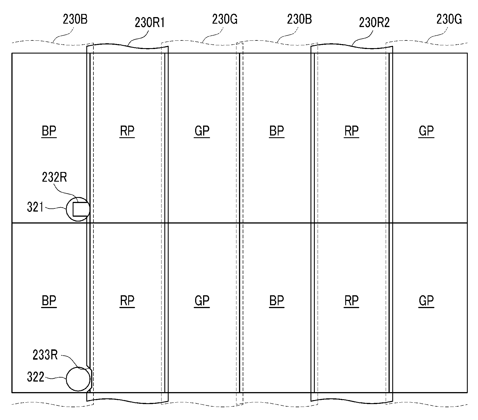
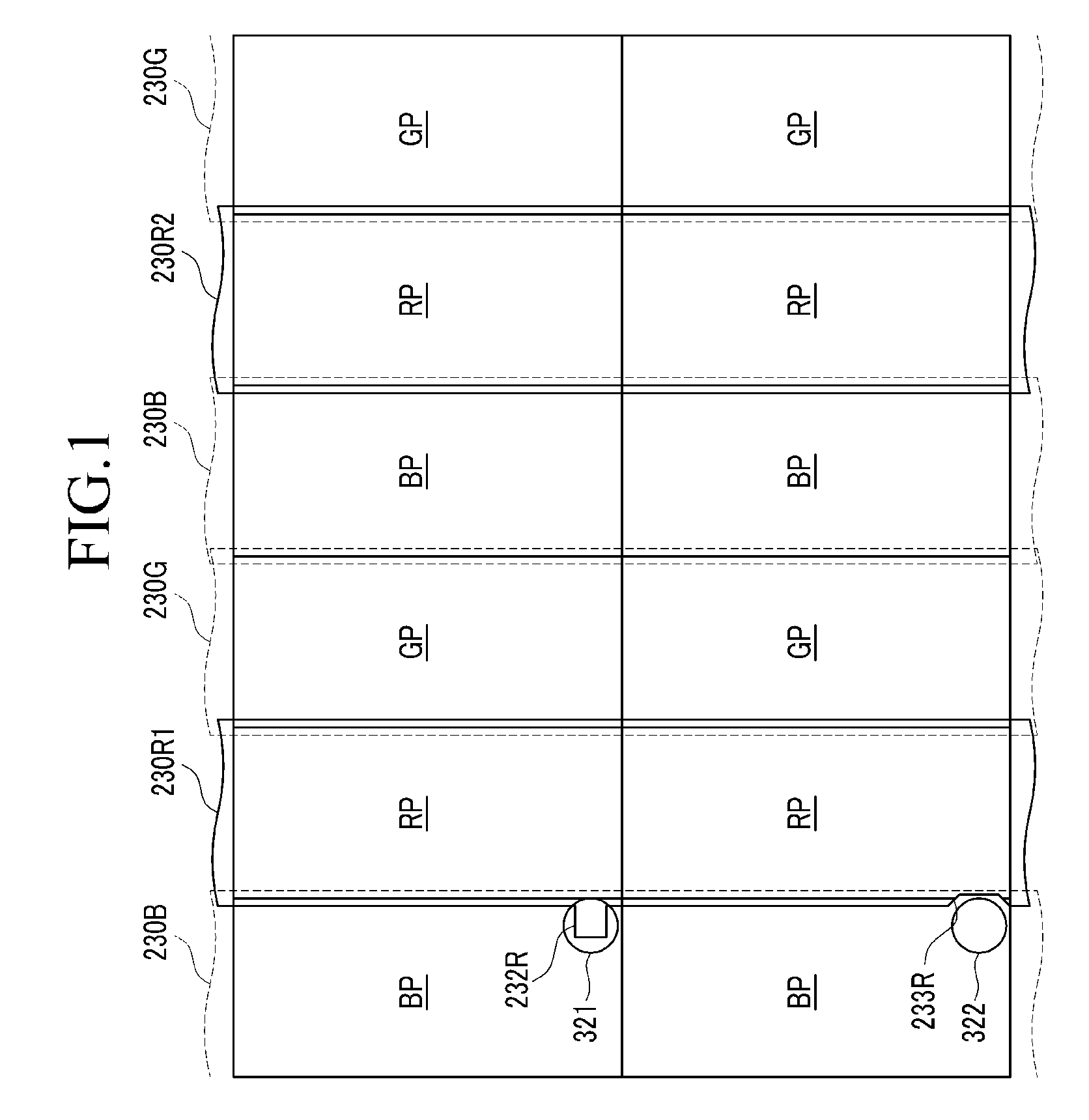
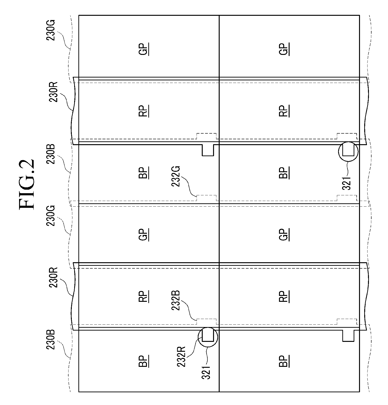
A liquid crystal display includes a first display panel including a first substrate, and first and second color filters disposed on the first substrate and adjacent to each other, a second display panel including a second substrate facing the first display panel and a first spacer disposed on the second substrate, and a liquid crystal layer disposed between the first and second display panels. The first color filter includes a first protrusion protruded toward and overlapped with the second color filter. The first spacer faces the first protrusion, and the first and second display panels contact each other at a location area of the first spacer.

Description

[0001]This application claims priority to Korean Patent Application No. 10-2008-0063522 filed on Jul. 1, 2008, and all the benefits accruing therefrom under 35 U.S.C. §119, the entire contents of which are incorporated herein by reference.BACKGROUND OF THE INVENTION[0002](a) Field of the Invention[0003]The present invention relates to a display device, and more particularly, to a liquid crystal display including color filters.[0004](b) Description of the Related Art[0005]Liquid crystal displays are now widely used as a flat panel display. A liquid crystal display has two display panels on which field generating electrodes, such as pixel electrodes and a common electrode are formed, and a liquid crystal layer that is interposed between the panels. In the liquid crystal display, voltages are applied to the field generating electrodes so as to generate an electric field over the liquid crystal layer, and the alignment of liquid crystal molecules of the liquid crystal layer is determine...

Claims


Application Information

Patent Timeline
Patent Type & Authority Applications(United States)
IPC IPC(8): G02F1/1335
CPCG02F1/13394G02F2001/13398G02F2201/503G02F2001/136231G02F2001/136222G02F1/13398G02F1/136222G02F1/136231G02F1/1335G02F1/136
Inventor KIM, HEE-JOONKIM, JOO-HANYOON, YEO-GEONSONG, JUN-HO
Owner SAMSUNG DISPLAY CO LTD
Why Eureka
Try Eureka