Pressure sensor

a pressure sensor and micro-machine technology, applied in the direction of liquid/fluent solid measurement, electronic circuit testing, instruments, etc., can solve the problems of temperature sensitivity, pressure in the reference chamber, and high cost of handling the very thin and therefore delicate monocrystalline diaphragm, etc., to achieve accurate and uniform thickness, accurate control and well-defined thickness

Inactive Publication Date: 2006-02-16
SILEX MICROSYST
View PDF12 Cites 26 Cited by
  • Summary
  • Abstract
  • Description
  • Claims
  • Application Information

AI Technical Summary

Benefits of technology

[0016] It is another object of the invention to provide a micromachined pressure sensor that is not affected or changes performance due to changes in the environment and to provide a method of manufacturing such a sensor.
[0018] It is another object of the invention to provide a designing and manufacturing process for fabricating a micromachined pressure sensor, which is suitable for volume production, i.e. a batch fabrication process, having a high yield.
[0022] It is another object of the invention to provide a micromachined pressure sensor having a diaphragm of an accurately uniform or constant thickness and to provide a method of manufacturing such a sensor.
[0024] By the fact that the diaphragm is obtained from an SOI-structure it can be given a very accurately defined and constant thickness since the interior oxide layer of the SOI-structure can be used as an etch stop layer. The diaphragm can be additionally thinned by etching but this is normally not necessary. In any case, such additional etching only has to remove a minor portion of the material of the diaphragm, this preserving substantially the uniformity of the thickness thereof. Since such additional etching only removes little material the etching process can be given well-defined characteristics to still give the diaphragm a very well-defined thickness.
[0029] The strain gauge can be located under the diaphragm, facing the cavity, this achieving a good protection of the strain gauge and a diaphragm having a flat and smooth outer surface.

Problems solved by technology

However, the handling of the very thin and therefore delicate monocrystalline diaphragms is very costly and can hardly be used in a process for mass fabrication.
There are also problems as to pressure in the reference chamber when using bonding methods, e.g. direct or fusion bonding.
A problem associated with vacuum sealing using direct fusion bonding is that even if the bonding is performed under a reduced pressure the residual gas pressure inside the reference cavity after bonding is considerably higher than the original chamber pressure, which in turn gives problem with the temperature sensitivity.
Vacuum sealing under UHV (Ultra High Vacuum) conditions is difficult and not suitable for production.
Another problem associated with direct fusion bonding includes voids between the bonded surfaces, due to problems with for example particles on the wafer surfaces before bonding.
This significantly decreases the process yield.
A problem associated with surface micromachining and the use of polycrystalline silicon is that the material properties are not optimized, such as the gauge factor in the strain gauges, the diffusion through the diaphragm etc.
A long process time including many steps is generally required.
Using machining as disclosed in this patent, the accuracy will not be very high.

Method used


Image

  • Pressure sensor
  • Pressure sensor
  • Pressure sensor

Examples


Embodiment Construction

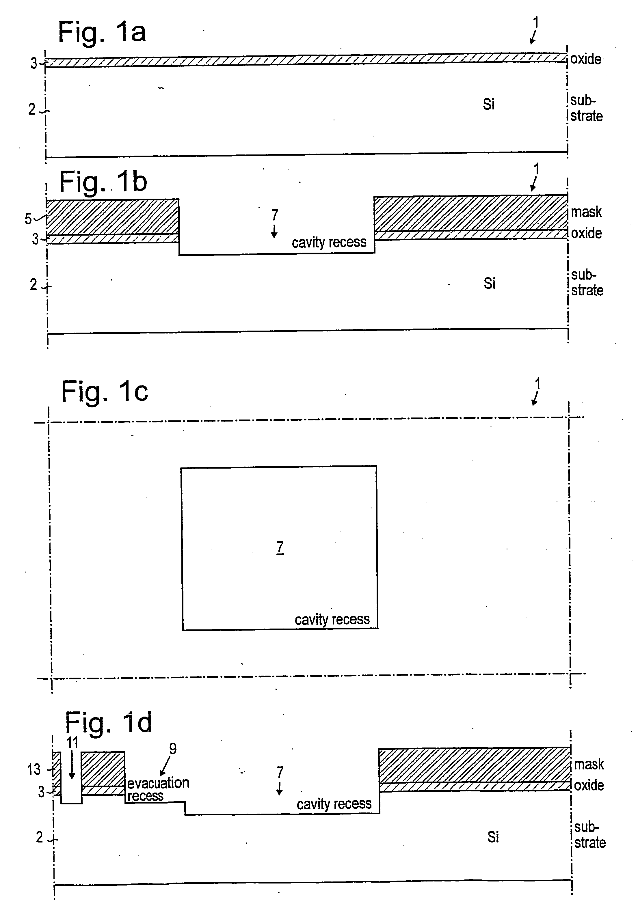
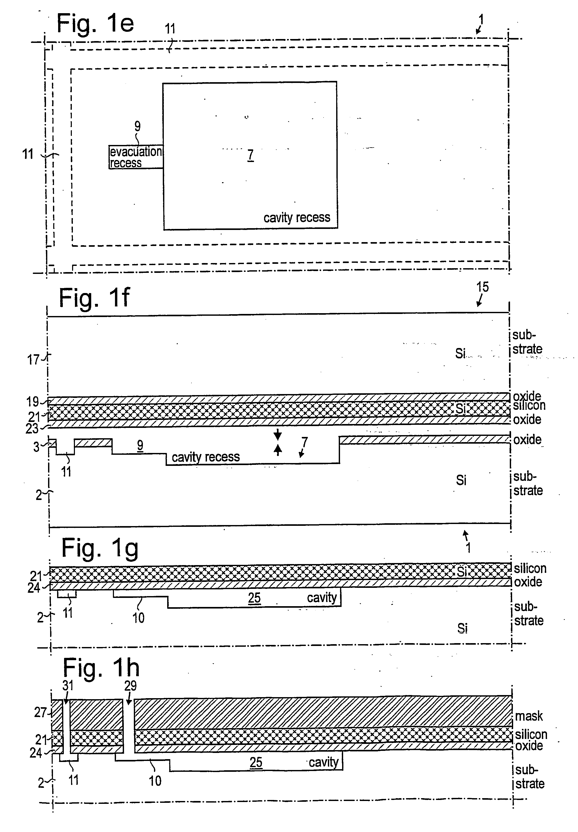
[0046] Methods of producing micromachined pressure sensors and the resulting pressure sensors having monocrystalline diaphragms obtained will now be described, the diaphragms in the various alternatives being obtained from an SOI-structure.

[0047] First an embodiment using a single SOI (Silicon On Insulator) structure will be described, this being the simplest alternative. The main advantage of all embodiments is the monocrystalline diaphragm that probably reduces the long-term drift of the sensor characteristics. Also, the monocrystalline structure is more resistive to moisture than other more porous materials such as polysilicon. A general advantage is the very well-defined and uniform thickness of the diaphragms in all embodiments, this giving the diaphragms desired elastic properties.

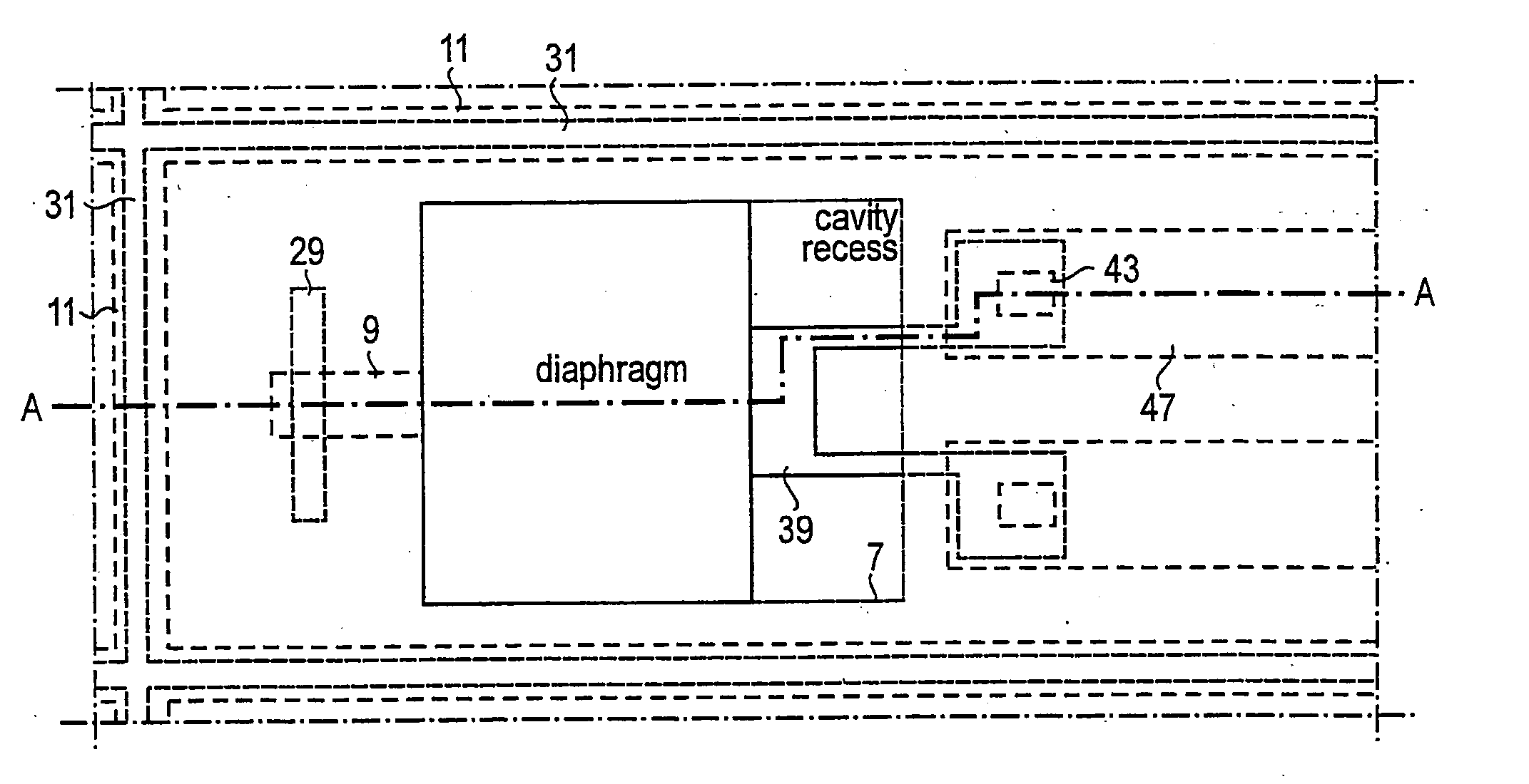
[0048] In the first embodiment a lower structure 1 is first produced by processing a silicon substrate such as a wafer 2, see FIG. 1a. A multitude of identical structures is produced in the followi...


PUM

PropertyMeasurementUnit
electrically conductingaaaaaaaaaa
pressureaaaaaaaaaa
vacuum pressureaaaaaaaaaa

Abstract

In manufacturing a pressure sensor a recess that will form part of the sensor cavity is formed in a lower silicon substrate. An SOI-wafer having a monocrystalline silicon layer on top of a substrate is bonded to the lower silicon substrate closing the recess and forming the cavity. The supporting substrate of the SOI-wafer is then etched away, the portion of the monocrystalline layer located above the recess forming the sensor diaphragm. The oxide layer of the SOI-wafer here acts as an “ideal” etch stop in the case where the substrate wafer is removed by dry (plasma) or wet etching using e.g. KOH. This is due to high etch selectivity between silicon and oxide for some etch processes and it results in a diaphragm having a very accurately defined and uniform thickness. The cavity is evacuated by forming a opening to the cavity and then sealing the cavity by closing the opening using LPCVD. Sensor paths for sensing the deflection of the diaphragm are applied on the outer or inner surface of the diaphragm. The monocrystalline diphragm gives the sensor a good long-term stability. Also the sensor path can be made of monocrystalline material, this giving the sensor even better good long-term characteristics. An increased sensitivity can be obtained by making active portions of the sensor paths freely extending, unsupported by other material of the pressure sensor, by suitable etching procedures.

Description

RELATED APPLICATION [0001] This application claims priority and benefit from Swedish patent application No. 0103471-9, filed Oct. 15, 2001, the entire teachings of which are incorporated herein by reference. TECHNICAL FIELD [0002] The present application relates to micromachined pressure sensors, in particular for in vivo use and attached to catheters, and to methods of manufacturing such sensors. BACKGROUND [0003] Pressure sensors generally contain movable or deformable bodies, most often a deflectable diaphragm, and they can be either of the main types absolute pressure sensors and differential or relative pressure sensors. An absolute pressure sensor measures a pressure in relation to a vacuum pressure, the latter one generally existing in a relatively small cavity located at one surface of the diaphragm, the pressure to be measured acting on the opposite surface. A differential pressure sensor measures the difference of two pressures acting on opposite surfaces of the diaphragm....

Claims


Application Information

Patent Timeline
Patent Type & Authority Applications(United States)
IPC IPC(8): H01S4/00G01L9/00
CPCG01L9/0042G01L9/0055Y10T29/49007Y10T29/49002Y10T29/49004
Inventor RANGSTEN, PELLEKALVESTEN, EDVARDMECHBACH, MARIANNE
Owner SILEX MICROSYST
Why Eureka
Try Eureka