

Supercooled water type dynamic ice slurry making system and ice making method
A dynamic ice slurry and cold water technology, applied in ice making, air conditioning system, ice making, etc., can solve the problems of large loss of cooling capacity, weakening of energy-saving advantages of supercooled water dynamic ice slurry production technology, and achieve preheating loss Reduction, significant energy saving benefits, and the effect of reducing the loss of preheating cooling capacity
- Summary
- Abstract
- Description
- Claims
- Application Information
AI Technical Summary
Problems solved by technology
Method used
Image

Examples
Embodiment 1
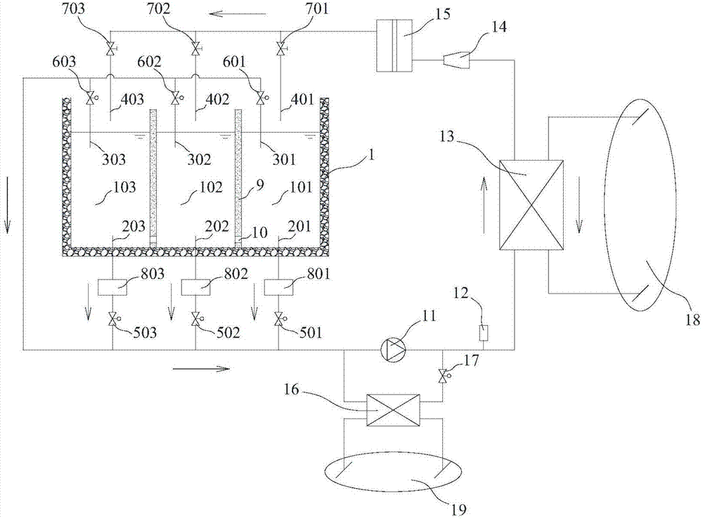
[0024] Such as figure 1As shown, the ice storage tank 1 is equally divided into three sub-tanks with equal volumes by the partition plate 9 , that is, the first sub-tank 101 , the second sub-tank 102 and the third sub-tank 103 . A first upper water intake pipe 301 and a first ice slurry pipe 401 are arranged above the first sub-tank 101 , and a first lower water intake pipe 201 is arranged below the first sub-tank 101 . A second upper water intake pipe 302 and a second ice slurry pipe 402 are arranged above the second sub-tank 102 , and a second lower water intake pipe 202 is arranged below the second sub-tank 102 . A third upper water intake pipe 303 and a third ice slurry pipe 403 are arranged above the third sub-tank 103 , and a third lower water intake pipe 203 is arranged below the third sub-tank 103 . The first, second and third lower water intake pipes are respectively provided with a first lower regulating valve 501 , a second lower regulating valve 502 and a third lo...
Embodiment 2
[0036]The above-mentioned embodiment 1 of the present invention is the situation that the ice storage tank is divided into three equal parts. In Embodiment 2, the ice storage tank can be equally divided into 2 sub-tanks or other number of sub-tanks equal to 2 or more. In other embodiments, step 1: arbitrarily select the Nth sub-tank and the Mth sub-tank, the N and the M are any different positive integers, select the Nth sub-tank for ice making, and use the Mth sub-tank The hot water in the sub-tank is heated and decrystallized, the lower regulating valve on the lower water intake pipe of the N sub-tank is opened, and the on-off valve on the ice slurry pipe is opened, and the lower regulating valve of the N sub-tank can be kept Adjust the state of the opening, keep the upper regulating valve of the Mth sub-slot in a state where the opening can be adjusted, and close all other valves; make the water flow from the Nth sub-slot through the cold water heat exchanger and the crysta...
PUM
 Abstract
Description
Claims
Application Information