Inverter parallel operation optimization control method

A technology of operation optimization and control method, applied in the direction of single grid parallel feeding arrangement, etc., can solve the problems of poor inverter control effect, deterioration of inverter power quality, affecting the normal operation of user equipment or electrical appliances, etc.

Inactive Publication Date: 2017-07-14
YUNNAN POWER GRID
View PDF5 Cites 19 Cited by
  • Summary
  • Abstract
  • Description
  • Claims
  • Application Information

AI Technical Summary

Problems solved by technology

[0004] However, due to the difference in the characteristics of the inverter itself, the difference in output power of multiple inverters in parallel operation will decrease with the increase of frequency and amplitude droop coefficient, but with the increase of droop coefficient, the output power of multiple inverters will decrease. The voltage deviation between inverters wil

Method used


Image

  • Inverter parallel operation optimization control method
  • Inverter parallel operation optimization control method
  • Inverter parallel operation optimization control method

Examples


Embodiment Construction

[0052] In order to enable those skilled in the art to better understand the technical solutions in the present invention, the technical solutions in the embodiments of the present invention will be clearly and completely described below in conjunction with the drawings in the embodiments of the present invention. Obviously, the described The embodiments are only some of the embodiments of the present invention, not all of them.

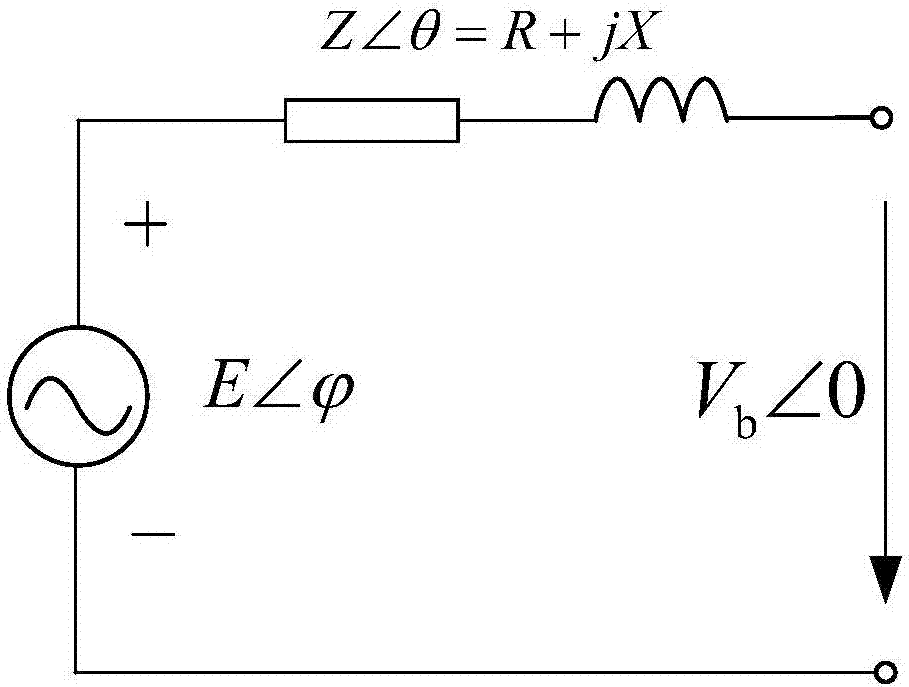
[0053] see figure 2 is the equivalent circuit diagram of parallel inverters, such as figure 2 shown, E and are the RMS value and power angle of the reference voltage; Z and θ are the modulus and impedance angle of the line impedance; R and X are the line resistance and inductance; V b is the effective value of the AC bus voltage.

[0054] From this, it can be obtained that the active power injected by the inverter into the parallel inverter system is:

[0055]

[0056] The reactive power is:

[0057]

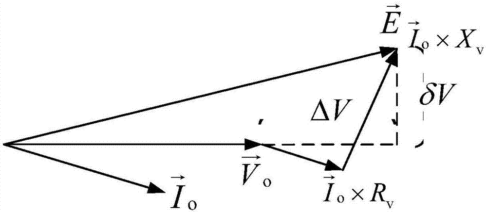
[0058] Suppose the introduced virtual...


PUM


Abstract

The invention provides an inverter parallel operation optimization control method. The method includes acquiring the rated capacity of each inverter in the parallel inverter system and the total load power factor angle of the parallel inverter system, determining the corresponding virtual impedance and sagging coefficient for each inverter according to the rated capacity and the total load power factor angle, determining the phase angle of each inverter based on the sagging coefficient, and then setting the same voltage amplitude for each inverter, determining the command voltage based on the voltage value, the virtual impedance, the phase angle, and the inverter output current, and controlling each inverter to output the active power and the reactive power according to the corresponding command voltage. The virtual impedance and sagging coefficient are determined by integrating the rated capacities of the inverters and the total load power factor angle of the parallel inverter system to realize the reasonable distribution of the active power and the reactive power of the inverters, the control effect of the inverters is optimized to reduce the voltage deviation, and the quality of the output energy of the inverters and the normal running of the user equipment or electric appliances are guaranteed.

Description

technical field [0001] The invention relates to the field of power electronic device control, in particular to an optimal control method for parallel operation of inverters. Background technique [0002] The inverter is a converter that converts DC power (battery, storage battery) into AC power (generally 220V, 50Hz sine wave). In the microgrid and UPS parallel redundant system, there are multiple inverters running in parallel. [0003] The control methods for parallel operation of parallel inverters mainly include: PQ control, constant voltage and constant frequency control, and droop control. Among them, droop control is a method of controlling the inverter by simulating the droop external characteristics of synchronous generators in the traditional power system. method. Such as figure 1 As shown, the main circuit of the circuit structure of the inverter adopting droop control in the parallel inverter system is a three-phase full-bridge circuit. The inverter output uses...

Claims


Application Information

Patent Timeline
IPC IPC(8): H02J3/38H02J3/46
CPCH02J3/38H02J3/46
Inventor 程军照王文玺黄梅刘宝林冯磊
Owner YUNNAN POWER GRID
Why Eureka
Try Eureka