Reaction cup arrangement system for magnetic particle chemiluminiscence immunity analyzer

A chemiluminescence immunoassay and cuvette technology, applied in scientific instruments, analytical materials, instruments, etc., can solve problems such as unfavorable detection process, low efficiency, slow detection speed, etc., to improve detection efficiency, great economic and practical value, and reduce labor. The effect of volume and labor intensity

Active Publication Date: 2017-07-18
CHONGQING KEYSMILE BIOLOGICAL TECH CO LTD
View PDF4 Cites 9 Cited by
  • Summary
  • Abstract
  • Description
  • Claims
  • Application Information

AI Technical Summary

Problems solved by technology

[0002] In biochemical experiments, the magnetic particle chemiluminescence immunoassay analyzer is usually used to detect and analyze body fluids. When using this instrument, the body fluids are usually put into the reaction cup first, and then the reaction cup is sent into the instrument for chemical analysis and detection. , to detect the reaction of the liquid to be tested in the reaction cup, especially in medicine, the reaction cup is often used to analyze the clinical chemical components of samples such as serum, plasma, urine, and cerebrospinal fluid in clinical tests. Many cuvettes are operated at the same time, and in the existing laboratory, it is often necessary to spend a lot of manpower to care and organize the cuvettes, and then put the cuvettes one by one into the reaction tank of the magnetic particle chemiluminescence immunoassay analyzer, which is relatively inefficient. It is not conducive to the realization of laboratory automation detection process, greatly reducing the detection speed

Method used


Image

  • Reaction cup arrangement system for magnetic particle chemiluminiscence immunity analyzer
  • Reaction cup arrangement system for magnetic particle chemiluminiscence immunity analyzer
  • Reaction cup arrangement system for magnetic particle chemiluminiscence immunity analyzer

Examples


Embodiment Construction

[0036] The present invention will be further described below in conjunction with embodiment and accompanying drawing.

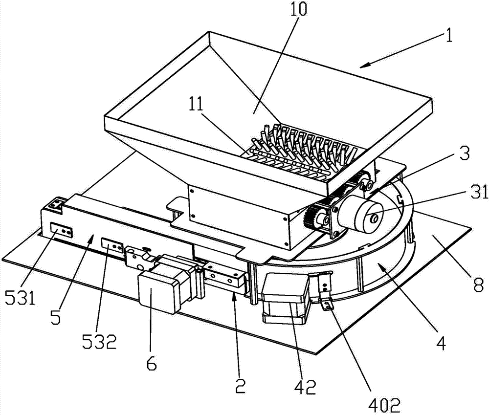
[0037] refer to figure 1 The reaction cup arrangement system for the magnetic particle chemiluminescence immunoassay analyzer mainly includes a drain cup device 1 and a turntable cup arrangement device 2. In this embodiment, the turntable cup arrangement device 2 is fixedly installed on the substrate 8, and the turntable cup arrangement device 2 mainly includes a centrifugal mechanism 4 and a cup discharge channel 5, and the leaking cup device 1 is detachably installed above the centrifugal mechanism 4.

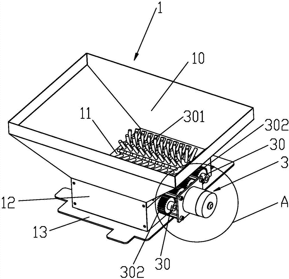
[0038] refer to figure 2 and image 3 The leaky cup device 1 includes an inverted cuvette chamber 10 in the shape of a truncated pyramid.

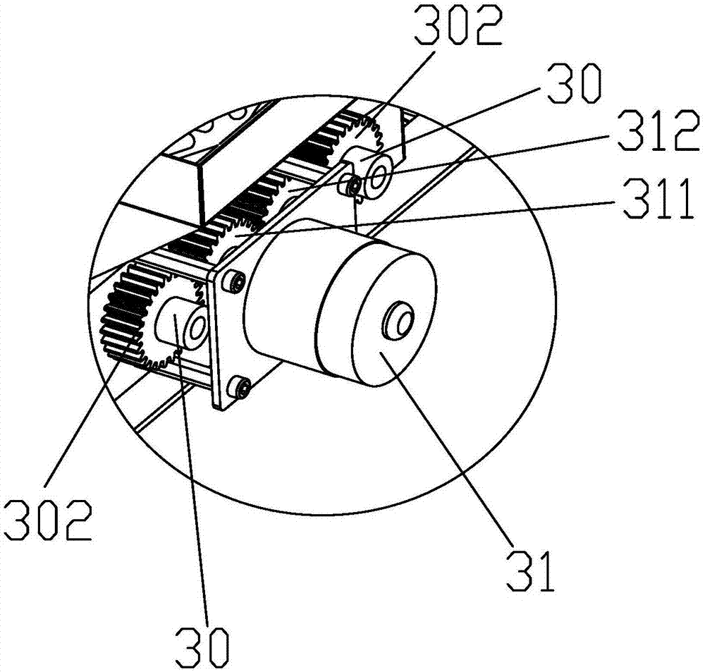
[0039] The bottom of the drain cup mouth 11 is provided with a rectangular parallelepiped installation head 12 extending downward along its side edge, and two wheel shafts 30 are rotatably arranged in the installatio...


PUM


Abstract

The invention discloses a reaction cup arrangement system for a magnetic particle chemiluminiscence immunity analyzer. The reaction cup arrangement system comprises a cup leaking device and a rotating disc cup arrangement device, wherein the cup leaking device comprises a reaction cup cabin; a cup leaking hole is formed in the bottom of the reaction cup cabin; an assistant cup leaking mechanism is arranged below the cup leaking hole; the rotating disc cup arrangement device comprises a centrifugal mechanism and a cup arrangement channel; the centrifugal mechanism is mainly used for conveying reaction cups into the cup arrangement channel; a limiting inlet for limiting the reaction cups to be fed in a lying manner is formed in the cup arrangement channel; a conveying device is arranged inside the cup arrangement channel; and a cup arrangement groove is formed in the cup arrangement channel. By adopting the scheme, a great number of reaction cups can be placed in the rotating disc cup arrangement device under control, the great number of the reaction cups are further rapidly arranged in an upright manner by using the rotating disc cup arrangement device, then the reaction cups can be taken and used by the analyzer, the detection efficiency of the analyzer is effectively improved, the workload and the working intensity are alleviated, great economic practical values can be achieved, and the automatic scientific development progress of laboratories can be accelerated.

Description

technical field [0001] The invention relates to the field of medical detection equipment, in particular to a reaction cup row system for a magnetic particle chemiluminescence immunoassay analyzer. Background technique [0002] In biochemical experiments, the magnetic particle chemiluminescence immunoassay analyzer is usually used to detect and analyze body fluids. When using this instrument, the body fluids are usually put into the reaction cup first, and then the reaction cup is sent into the instrument for chemical analysis and detection. , to detect the reaction of the liquid to be tested in the reaction cup, especially in medicine, the reaction cup is often used to analyze the clinical chemical components of samples such as serum, plasma, urine, and cerebrospinal fluid in clinical tests. Many cuvettes are operated at the same time, and in the existing laboratory, it is often necessary to spend a lot of manpower to care and organize the cuvettes, and then put the cuvettes...

Claims


Application Information

Patent Timeline
Patent Type & Authority Applications(China)
IPC IPC(8): G01N35/04G01N33/53
CPCG01N33/5302G01N35/04
Inventor 胡晓雷邱胜
Owner CHONGQING KEYSMILE BIOLOGICAL TECH CO LTD
Why Eureka
Try Eureka