Valve-valve guide friction pair wear test device and test method

A valve guide and testing device technology, which is used in measuring devices, engine testing, mechanical component testing, etc., can solve the problems of insufficient consideration of actual wear patterns, lengthy cycles, and complicated testing.

Active Publication Date: 2017-07-28
SOUTH CHINA UNIV OF TECH
View PDF10 Cites 4 Cited by
  • Summary
  • Abstract
  • Description
  • Claims
  • Application Information

AI Technical Summary

Problems solved by technology

[0003] The research on valve guide wear at home and abroad mainly focuses on valve guide material selection, valve guide material wear and valve guide wear test. Among them, the research on valve guide material wear is usually carried out by using traditional material wear testing machine, which only focuses on the characteristics of the material itself, and it is not sufficient. Considering its actual wear form; while the wear test of the valve-valve guide friction pair is usually carried out on the whole engine test, the cycle is long and the test is complicated

Method used


Image

  • Valve-valve guide friction pair wear test device and test method
  • Valve-valve guide friction pair wear test device and test method
  • Valve-valve guide friction pair wear test device and test method

Examples


Embodiment 1

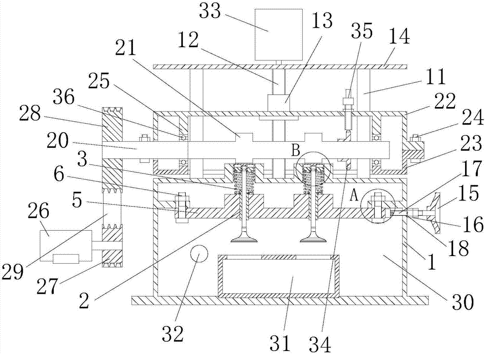
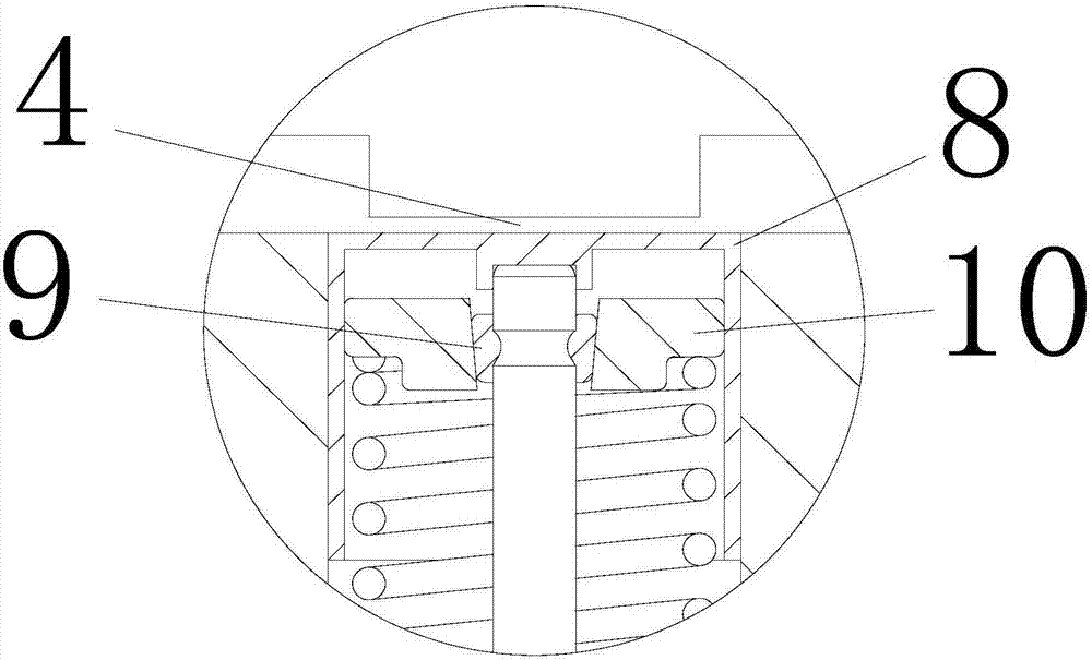
[0036] A wear test device for a valve-valve guide friction pair, comprising a frame 1, a valve guide 2, a guide force device, a valve return spring 3, a valve clearance adjustment device and a valve driving device for driving the valve to move, the valve clearance adjustment The device is connected with the valve driving device for adjusting the valve clearance 4;

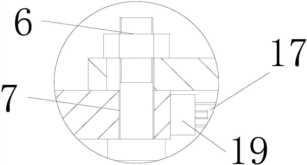
[0037] The conduit booster device includes a booster seat 5, a locking bolt 6 and a force applying mechanism for pushing the booster seat. A conduit installation hole is opened on the booster seat, and the valve guide is installed in the conduit installation hole. Adjustment holes are provided, and the locking bolts pass through the adjustment holes respectively and are fixed to the frame, and an adjustment space 7 is formed between the adjustment holes and the locking bolts;

[0038] The middle part of the valve stem of the valve is passed through the valve guide, and the two ends of the valve return spring are re...

Embodiment 2

[0062] A wear test method of the valve-valve guide friction pair, a method of controlling the horizontal loading force: the force application mechanism pushes the force-added seat, and the force-added seat moves within the range of the adjustment space, and the valve is controlled by controlling the thrust applied by the force-apply mechanism the contact pressure between the guide tube and the valve stem of the valve;

[0063] The method of adjusting the valve clearance: the screw drive mechanism drives the screw to rotate, drives the screw nut to drive the drive device mounting frame to move up or down, and drives the camshaft to move away from or close to the valve when the drive device mounting frame moves, thereby adjusting the size of the valve clearance ;

[0064] When testing the influence of the horizontal loading force on the amount of wear, adjust the valve clearance to the set value; then, make the force applying mechanism apply the set horizontal loading force to t...


PUM


Abstract

The invention discloses a valve-valve guide friction pair wear test device and test method. The valve-valve guide friction pair wear test device comprises a frame, a valve guide, a guide force application device, a valve reset spring, a valve clearance adjustment device and a valve driving device for driving a valve to move. The valve clearance adjustment device is connected with the valve driving device and is used for adjusting valve clearance; the middle portion of a valve rod of the valve is arranged in the valve guide; and the two ends of the valve reset spring are connected with the upper portion of the valve rod of the valve and a force application base. The test method and device solve the problems of lengthy and complex inspection cycle of the engine overall bench test and actual engine, can finish wear performance evaluation of a valve-valve guide friction pair in a short test period and provide reliable basis for actual production.

Description

technical field [0001] The invention relates to a wear test device and a test method, in particular to a wear test device and a test method of a valve-valve guide friction pair. Background technique [0002] The valve guide is the guiding device of the engine valve, which guides the valve. In the valve mechanism of the engine, the valve guide not only has a high working temperature, but also bears the horizontal force of the valve. During the operation of the engine, the valve and the valve guide produce high-frequency reciprocating impact friction, which is prone to wear and tear. The wear of the valve and the valve guide can cause the gap between them to increase, thereby causing the valve to vibrate during the reciprocating movement, resulting in The valve guide fractured and failed. Therefore, the wear performance of the valve guide deeply affects the output power, combustion performance and service life of the engine. [0003] The research on valve guide wear at home...

Claims


Application Information

Patent Timeline
Patent Type & Authority Applications(China)
IPC IPC(8): G01M15/02G01M13/00G01N3/56G01N3/02
CPCG01M13/00G01M15/02G01N3/02G01N3/56
Inventor 屈盛官肖传伟赖福强尹联民李小强
Owner SOUTH CHINA UNIV OF TECH
Why Eureka
Try Eureka