Eureka AIR delivers breakthrough ideas for toughest innovation challenges, trusted by R&D personnel around the world.

Valve wear test device

A wear test, valve technology, applied in the direction of testing wear resistance, etc., can solve problems such as difficult diagnosis of faults, complicated test process, leakage, etc., to achieve the effects of making up for easy leakage, avoiding lengthy cycles, and accurate test results

Inactive Publication Date: 2015-07-29
SOUTH CHINA UNIV OF TECH
View PDF7 Cites 9 Cited by
  • Summary
  • Abstract
  • Description
  • Claims
  • Application Information

AI Technical Summary

Problems solved by technology

[0003] The research on valve wear at home and abroad mainly focuses on valve material selection, valve material wear and valve wear test. Among them, the research on valve material wear is usually carried out by using traditional material wear testing machine, which only focuses on the characteristics of the material itself, and does not fully consider the actual situation of the valve. The wear mode; while the valve wear test usually implements the whole engine test, which leads to a long test period and a complicated test process
[0004] There is a valve test device using hydraulic loading in China, but the hydraulic loading system has a lot of energy loss during the working process, is sensitive to temperature changes, and is prone to leakage. At the same time, the fault is difficult to diagnose and not easy to maintain

Method used


Image

  • Valve wear test device
  • Valve wear test device
  • Valve wear test device

Examples


Embodiment 1

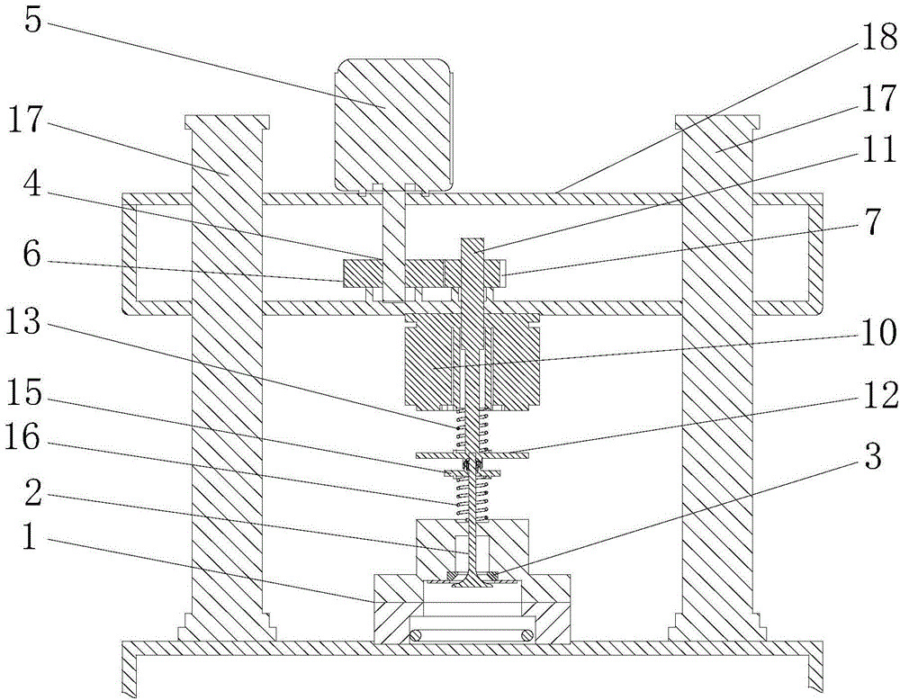
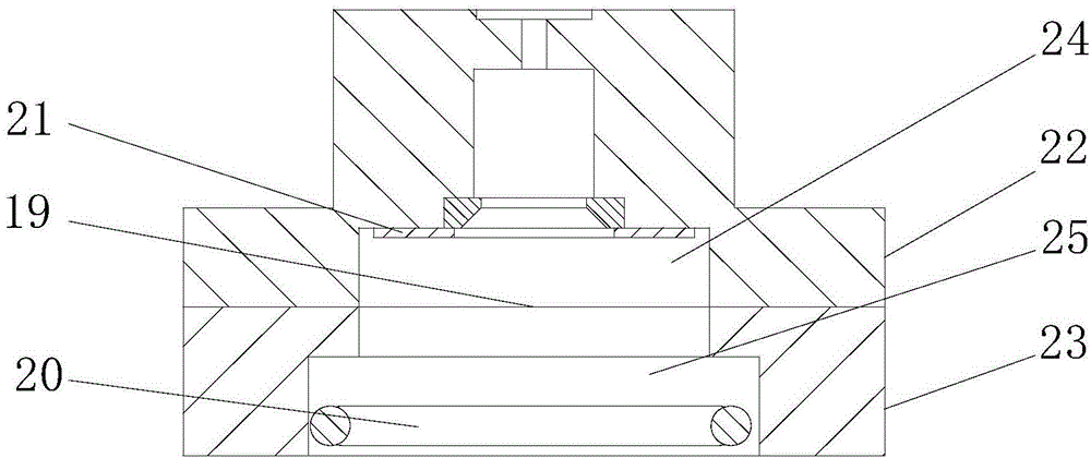
[0025] A valve wear test device includes a combustion chamber 1, a valve 2, a valve seat ring 3 and a rotating device 4 that drives the valve 2 to rotate, the rotating device includes a motor 5, a driving gear 6 and a driven gear 7, the The motor is connected to the driving gear, the driving gear is meshed with the driven gear, the driving rod is connected to the driven gear, the valve seat is arranged in the combustion chamber, and the valve passes through the valve seat Protruding into the combustion chamber, the valve face of the valve is in contact with the valve seat ring during testing.

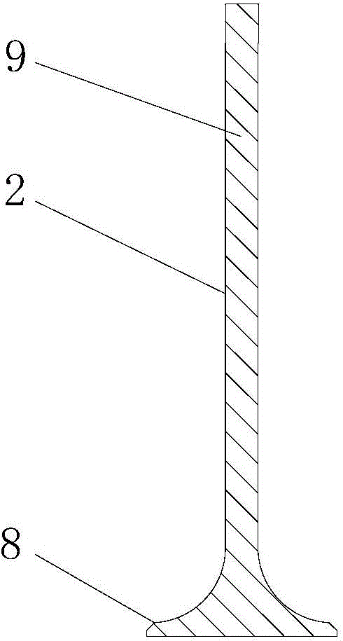
[0026] Preferably, it also includes an electromagnetic closing mechanism that keeps the valve face 8 of the valve in contact with the valve seat ring during the test, and the valve stem 9 of the valve extends out of the combustion chamber and is connected with the electromagnetic closing mechanism. Preferably, the electromagnetic closing mechanism includes a magnetic base 10, a driving ...


PUM


Abstract

The invention discloses a valve wear test device. The valve comprises a combustion chamber, a valve, a valve seat ring and a rotating device for driving the valve to rotate, wherein the valve seat ring is arranged in the combustion chamber, the valve penetrates through the valve seat ring to extend into the combustion chamber, and during testing, one valve surface of the valve is contacted with the valve seat ring. The device overcomes the defects of whole engine tests, the long actual engine comprehensive survey period and complexity, overcomes defects that hydraulic loading can cause leakage easily and the like, can finish wear characteristic evaluation of the valve in an extremely short test period and provides a reliable basis for actual production.

Description

technical field [0001] The invention relates to the field of valve wear test, in particular to a valve wear test device. Background technique [0002] In the engine, the valve-valve seat friction pair works in a harsh environment with high stress, high temperature and corrosiveness, and is prone to wear. At the same time, the assembly error of the valve and the rotation during opening and closing aggravate this wear. Valve wear can cause serious consequences such as valve sinking, valve clearance disappearing, gas leakage, etc., which not only reduces the power of the engine, but also increases the fuel consumption rate. Therefore, the wear performance of the valve deeply affects the output power, combustion performance and service life of the engine. [0003] The research on valve wear at home and abroad mainly focuses on valve material selection, valve material wear and valve wear test. Among them, the research on valve material wear is usually carried out by using tradit...

Claims


Application Information

Patent Timeline
IPC IPC(8): G01N3/56
Inventor 屈盛官熊志华王光宏赖福强李小强
Owner SOUTH CHINA UNIV OF TECH
Why Eureka
Eureka Blog
Learn More