
Grouting bottom-sealing structure and construction technology of deep foundation pit in high-pressure water-thick sandy pebble stratum

A grouting back cover and high pressure bearing technology, applied in infrastructure engineering, construction, etc., can solve the problems of foundation leakage, long construction period, large grouting volume, etc., and achieve the effect of slow construction period and huge cost

Active Publication Date: 2016-05-11
RANKEN RAILWAY CONSTR GROUP +1
View PDF5 Cites 0 Cited by
  • Summary
  • Abstract
  • Description
  • Claims
  • Application Information

AI Technical Summary

Problems solved by technology

[0006] The purpose of the present invention is to provide a deep foundation pit grouting sealing structure and its construction technology in sand and pebble strata with high pressure water thickness, so as to solve the problems of large grouting volume, high cost and long construction period in the existing method of grouting and sealing the whole range of base , there is a water leak in the basement, and the groundwater rushes to the rock and soil layer on the basement, and it is difficult to judge the problem of the leaking part

Method used


Image

  • Grouting bottom-sealing structure and construction technology of deep foundation pit in high-pressure water-thick sandy pebble stratum
  • Grouting bottom-sealing structure and construction technology of deep foundation pit in high-pressure water-thick sandy pebble stratum
  • Grouting bottom-sealing structure and construction technology of deep foundation pit in high-pressure water-thick sandy pebble stratum

Examples


Embodiment

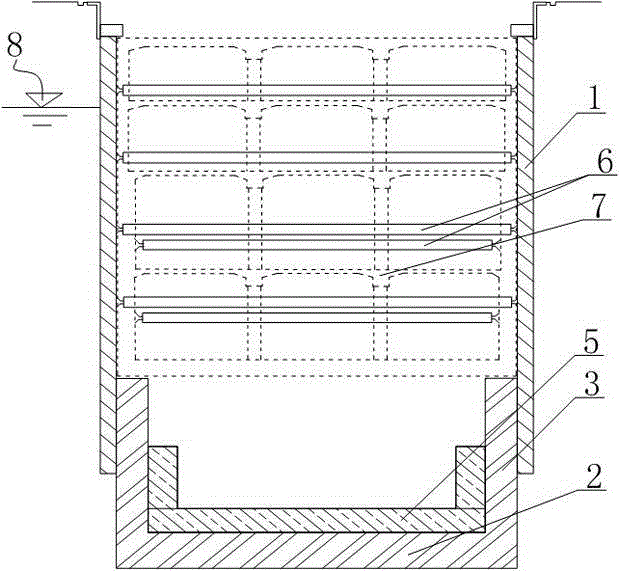
[0038] This embodiment is a station of the Beijing subway, its length is 139.2m, the depth of the foundation pit of the standard section is 31.6m, and the width is 24.9m. The floor of the station is mainly located on the pebble layer with strong water permeability, and the confined water level outside the pit is 13m away from the bottom of the pit.

[0039] According to the existing technology in the basement full-scale grouting and back-sealing scheme: the enclosure structure adopts a 1.0m thick underground diaphragm wall, the embedded depth is 15m, and the sleeve valve pipe is used for full-scale grouting within the 15m range of the basement. Inject double liquid slurry in the range of 3m, such as Figure 4 shown. It is estimated that the construction cost of the enclosure structure is about 62.29 million, the grouting cost is 112.8 million, and the grouting construction period is 3 months.

[0040] In the actual construction process, the construction structure is as follo...


PUM


Abstract

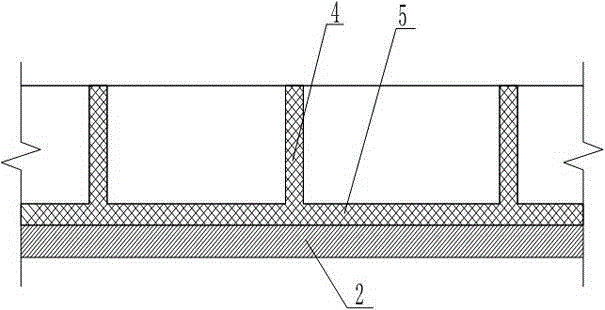
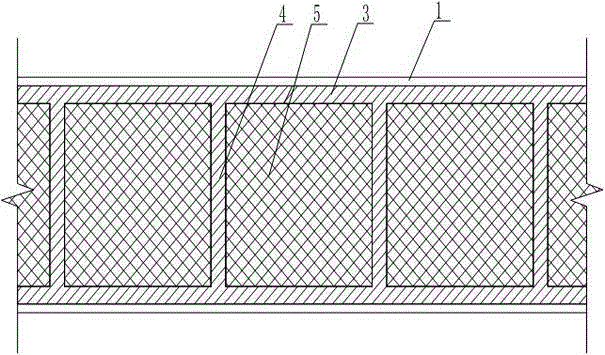
The invention discloses a high-pressure-bearing water and thick sand and pebble formation deep foundation pit grouting bottom-sealing structure and a construction technology thereof. The high-pressure-bearing water and thick sand and pebble formation deep foundation pit grouting bottom-sealing structure comprises a waterproof curtain which is inserted into the ground; a slurry base plate, a slurry side wall and a slurry separation wall are formed below the waterproof curtain through grouting; the slurry side wall and the waterproof curtain are cemented closely; the slurry base plate, the slurry side wall and the slurry separation wall surround a base to form a plurality of U-shaped grouting cabins which are concaved downward; a slurry reinforcement layer is formed above the slurry base plate through secondary grouting. According to the high-pressure-bearing water and thick sand and pebble formation deep foundation pit grouting bottom-sealing structure and the construction technology thereof, the integral strength and stiffness of the pit bottom is increased through the U-shaped grouting cabin structure, the double functions of pit bottom reinforcement and seepage control are achieved, the problems of the effect on the stability of the pit bottom due to the buried depth increased high-pressure-bearing water and the pit bottom uplift caused by foundation pit excavation can be effectively solved, and meanwhile the lateral displacement of the pit wall and the settlement deformation of the surrounding environment are reduced well.

Description

technical field [0001] The invention relates to the field of pressurized water treatment of deep foundation pit engineering in thick sandy pebble formations, in particular to a grouting bottom sealing structure and construction technology for deep foundation pits in thick sandy pebble formations with high pressure water. Background technique [0002] At present, in deep foundation pit engineering, three methods are usually used to solve the engineering problems caused by confined water, such as precipitation outside the pit, vertical partition of curtain, and full grouting of the base. [0003] The first is the method of dewatering outside the pit. The design idea of ​​this method is: use underground diaphragm walls or bored piles, occlusal piles, and corresponding water-stop curtains as the enclosure structure. Confined water construction, the foundation pit excavation will be carried out after the confined water head drops to the elevation required by the design. The adva...

Claims


Application Information

Patent Timeline
Patent Type & Authority Patents(China)
IPC IPC(8): E02D19/16
CPCE02D19/16E02D19/18
Inventor 刘建伟卢致强潘秀明雷崇红吕高峰张建海贺长俊崔志杰郝志宏李铁生申小兵付波张美琴孟伟李明磊刘静涛刘卫华谭万忠贾飞宇高雄鹰陈琪娇
Owner RANKEN RAILWAY CONSTR GROUP
Learn More