
Identification method for beam structure damage of vibration mode weighing modal flexibility
A technology of damage identification and beam structure, applied in the analysis of solids using sonic/ultrasonic/infrasonic waves, it can solve the problems of inability to carry out damage degree, damage location, identification, etc., and achieve the effect of accurately identifying the damage degree
- Summary
- Abstract
- Description
- Claims
- Application Information
AI Technical Summary
Problems solved by technology
Method used
Image

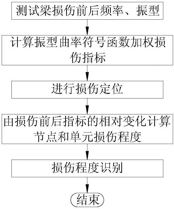
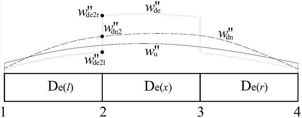

Examples
Embodiment 1
[0128] Embodiment one: see image 3 , is a simply supported beam with a span of 10m and is equally divided into 20 units (the numbers in the upper circle in the figure are the unit numbers, and the lower numbers are the node numbers). The cross-sectional size is b×h=300mm×500mm, and the elastic modulus of the material is E=3.25×10 4 MPa, the density is 2500kg / m 3 . The damage of the unit is simulated by the reduction of the elastic modulus, and the damage conditions of the beam structure are shown in Table 1:
[0129] Table 1 Damage conditions of simply supported beams
[0130]
[0131] The specific implementation steps are as follows:
[0132] Step 1: Obtain the first three vertical frequencies and mode shapes of the simply supported beam before and after damage through finite element model simulation analysis.
[0133] Step 2: Calculate the weighted damage index of the mode shape curvature sign function according to the frequency and mode shape before and after the d...
Embodiment 2
[0135] Embodiment two: see Figure 8 , is a three-span continuous beam finite element model, its span layout is 10m+15m+10m, 1.0m is divided into one unit, a total of 35 units, 36 nodes, (the number in the upper circle in the figure is the unit number, The numbers in the lower row are node numbers). The cross-sectional size is b×h=300mm×500mm, and the elastic modulus of the material is E=3.25×10 4 MPa, the density is 2500kg / m 3 . The damage of the unit is simulated by the reduction of the elastic modulus, and the damage conditions of the beam structure are shown in Table 2:
[0136] Table 2 Damage conditions of three-span continuous beams
[0137]
[0138] The specific implementation steps are as follows:
[0139] Step 1: Obtain the first three vertical frequencies and mode shapes of the three-span continuous beam before and after damage through finite element model simulation analysis.
[0140] Step 2: Calculate the weighted damage index of the mode shape curvature s...
PUM
 Abstract
Description
Claims
Application Information