Damage Identification Method for Continuous Beams Based on Curvature of Lines Influenced by Support Reactions
What is AI technical title?
AI technical title is built by Patsnap AI team. It summarizes the technical point description of the patent document.
A support reaction force and damage identification technology, applied in instrumentation, geometric CAD, design optimization/simulation, etc., can solve problems such as failure to identify the degree of structural damage
Active Publication Date: 2021-05-25
XIANGTAN UNIV
View PDF0 Cites 0 Cited by
Summary
Abstract
Description
Claims
Application Information
AI Technical Summary
This helps you quickly interpret patents by identifying the three key elements:
Problems solved by technology
Method used
Benefits of technology
Problems solved by technology
[0005] The purpose of the present invention is to provide a continuous beam damage identification method for the curvature of the influence line of support reaction force in view of the deficiency that the existing support reaction force influence line method cannot identify the degree of structural damage
Method used
Image
Click on the blue label to locate the original text in one second.
Reading with bidirectional positioning of images and text.
Examples
Embodiment 1
[0147] Embodiment one: see Figure 5 , taking a plexiglass plate model to simulate two-span continuous beams as an example, the span layout is 50+50cm, and 5cm is divided into a unit, a total of 20 units and 21 measuring points (the numbers in the upper circle in the figure are the unit numbers, The numbers in the lower row are the support numbers, and the numbers of the left and right measuring points of unit i are respectively i, i+1). The cross-sectional size is b×h=4.5cm×1.5cm, and the elastic modulus of the material is 2.7×10 3 MPa, Poisson's ratio is 0.37, density is 1200kg / m 3 .
[0148] The damage in the actual engineering structure, such as the generation of cracks, material corrosion or the reduction of elastic modulus, generally only causes a large change in the structural stiffness, but has little impact on the quality of the structure. Therefore, in the finite element calculation, it is assumed that the damage of the structural element only causes the decrease ...
Embodiment 2
[0163] Embodiment two: Simulate a three-span continuous beam with a plexiglass plate model as an example, as Figure 19 As shown, the span layout is 50+75+50cm, 5cm is divided into one unit, a total of 35 units, 36 measuring points (the numbers in the upper circle in the figure are the unit numbers, the lower numbers are the support numbers, unit i The numbers of the left and right measuring points are respectively i, i+1). Section dimensions and material parameters refer to the two-span continuous beam calculation example.
[0164] 1) Single damage situation
[0165] The damage conditions are shown in Table 3, in which unit 1 is located near the 1# support at the left end of the first span, unit 18 is the mid-span unit of the middle span, and unit 26 is located near the 3# support at the left end of the third span where the negative bending moment is the largest.
[0166] Table 3 Single damage condition of three-span continuous beam
[0167]
[0168] The DI index of wor...
PUM
Abstract
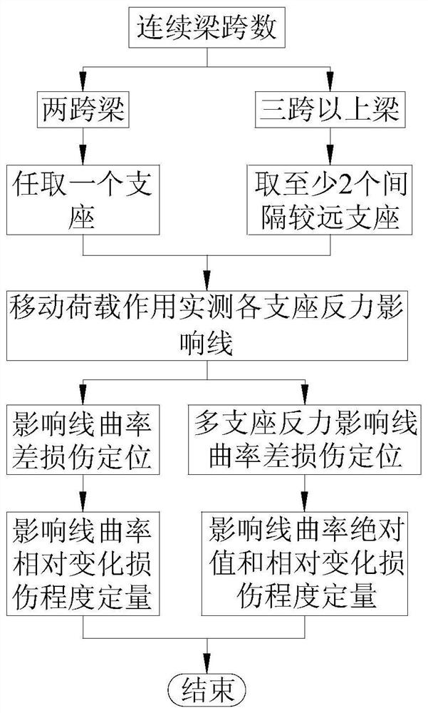
The invention discloses a continuous beam damage identification method for the curvature of the support reaction force influence line, the steps are as follows: respectively apply moving loads to the continuous beam before and after the damage, and obtain the measured support reaction force influence line before and after the continuous beam damage; The curvature of the support reaction force influence line before and after the beam damage is calculated, and the damage location is performed by the curvature difference of the support reaction force influence line; the damage degree is quantified by the relative change of the support reaction force influence line curvature before and after the continuous beam damage; if the continuous beam span If the number is greater than 2, the absolute value of the curvature of multiple support reaction force influence lines before and after damage and the damage degree are quantified. The invention has low requirements on the number of measuring points, saves the amount of monitoring sensors, can accurately locate and quantify the damage of the continuous beam structure, and is applied to the damage assessment of the continuous beam structure.
Description
technical field [0001] The invention belongs to the technical field of structural health monitoring, and in particular relates to a continuous beam damage identification method for the curvature of a support reaction force influence line of the beam structure non-destructive testing technology. Background technique [0002] In recent years, there are more and more old bridges in our country, and the problems are becoming more and more obvious. Many existing bridges can no longer meet the functional requirements, and safety accidents such as bridge breakage and collapse occur from time to time. Scholars in the field of civil engineering have gradually realized the importance of health monitoring and safety assessment of bridge structures, and have studied various damage identification technologies. . Structural damage identification is an important part of the bridge structural health monitoring system. At present, there are two main types of damage identification methods. O...
Claims
Application Information
Patent Timeline
Application Date:The date an application was filed.
Publication Date:The date a patent or application was officially published.
First Publication Date:The earliest publication date of a patent with the same application number.
Issue Date:Publication date of the patent grant document.
PCT Entry Date:The Entry date of PCT National Phase.
Estimated Expiry Date:The statutory expiry date of a patent right according to the Patent Law, and it is the longest term of protection that the patent right can achieve without the termination of the patent right due to other reasons(Term extension factor has been taken into account ).
Invalid Date:Actual expiry date is based on effective date or publication date of legal transaction data of invalid patent.

