Al technical title is built by PatSnap Al team. It summarizes the technical point description of the patent document.
A heater and shell technology, applied in the field of air purification, can solve the problems of large space occupation, achieve stable flow direction, reduce noise, and achieve the effects of heating efficiency
Active Publication Date: 2019-10-18
CHENGDU YANGZHONG NEW ENERGY TECH
View PDF9 Cites 0 Cited by
Summary
Abstract
Description
Claims
Application Information
AI Technical Summary
This helps you quickly interpret patents by identifying the three key elements:
Problems solved by technology
Method used
Benefits of technology
Problems solved by technology
In view of the defects of existing purifiers, the applicant combined the purifying function and heating function of the air purifier to solve the problem of excessive indoor space occupation; when in use, the columnar structure formed by the upper arc plate and the lower arc plate is placed horizontally In the middle of the profiling shell, the air enters from the air inlet, and the air is purified after the multi-stage filtration of the purification mechanism, and on the metal heat sink connected to the lower arc plate, the heating element starts to heat the purified air, Through the rotation of the impeller, the heated fresh air overflows from the air outlet to realize indoor heating and air purification, which greatly reduces the occupation of indoor space; among them, the combination of the upper shell and the lower shell constitutes The profiling shell can be made into a variety of different styles to increase the visual sense of the air purifier
Method used
Image
Click on the blue label to locate the original text in one second.
Reading with bidirectional positioning of images and text.
Examples
Embodiment 1
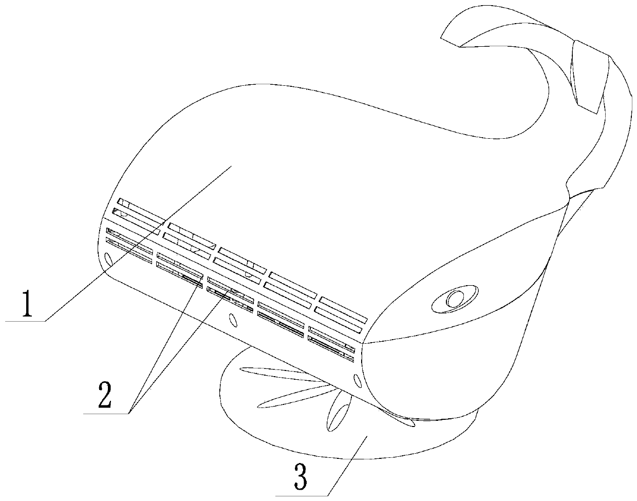
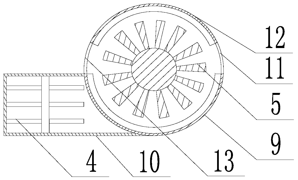
[0024] Such as Figure 1 ~ Figure 4 As shown, this embodiment includes a profiling housing 1, the profiling housing 1 includes an upper housing and a lower housing bolted to the upper housing, a foot 3 is installed at the bottom of the lower housing, and the One side wall of the lower housing is provided with an air inlet 8, the other side wall of the lower housing is provided with a plurality of through holes, and the side wall of the upper housing is provided with a plurality of small holes on the same side as the through holes. holes, and a plurality of said through holes and small holes form the air outlet 2, inside the said profiling shell 1 are fixed with arc-shaped upper arc plate 12, lower arc plate 9, fan 6 is fixed on the profiling shell On the inner wall of the body 1, the impeller 5 of the fan 6 is placed between the upper arc plate 12 and the lower arc plate 9, and the inner walls of the upper arc plate 12 and the lower arc plate 9 are equipped with Matching soun...
PUM
Abstract
The invention discloses a silenced warmer. The silenced warmer comprises a profile housing, wherein air inlets are formed in one sidewall of the lower housing, and a plurality of through holes are formed in the other sidewall of the lower housing; a plurality of pores are formed in the sidewall of the upper housing, and the plurality of through holes and the pores form air outlets; an upper arc plate and a lower arc plate are fixed into the profile housing; a draught fan is fixed to the inner wall of the profile housing; a flow guide hole I which faces the air outlets and a flow guide hole II which faces the air inlets are correspondingly formed between two opposite end parts of the upper arc plate and the lower arc plate; a heat dissipating rack I in which a heating body is arranged is mounted at one side, close to the air outlets, of the lower arc plate. According to the silenced warmer, air enters through the air inlets and is purified by multi-stage filtering through a purifying mechanism, then the purified air is heated through the heating body, and finally the heated clean air overflows through the air outlets with the rotating of impellers, so that the indoor warming and the air purifying can be achieved, and the used indoor space can be reduced.
Description
technical field [0001] The invention relates to the field of air purification, in particular to a sound-absorbing heater. Background technique [0002] Air purifiers, also known as "air cleaners", air fresheners, and purifiers, refer to decoration pollution that can absorb, decompose or transform various air pollutants (generally including PM2.5, dust, pollen, odor, formaldehyde, etc.) , bacteria, allergens, etc.), home appliances that effectively improve air cleanliness, are mainly divided into household, commercial, industrial, and building. [0003] There are many different technologies and media in an air purifier that enable it to provide clean and safe air to the user. Commonly used air purification technologies include: adsorption technology, negative (positive) ion technology, catalytic technology, photocatalyst technology, superstructure photomineralization technology, HEPA high-efficiency filtration technology, electrostatic dust collection technology, etc.; mater...
Claims
Application Information
Patent Timeline
Application Date:The date an application was filed.
Publication Date:The date a patent or application was officially published.
First Publication Date:The earliest publication date of a patent with the same application number.
Issue Date:Publication date of the patent grant document.
PCT Entry Date:The Entry date of PCT National Phase.
Estimated Expiry Date:The statutory expiry date of a patent right according to the Patent Law, and it is the longest term of protection that the patent right can achieve without the termination of the patent right due to other reasons(Term extension factor has been taken into account ).
Invalid Date:Actual expiry date is based on effective date or publication date of legal transaction data of invalid patent.