Sticker pressure foot and sewing machine with same

A technology of sticking strips and presser feet, which is applied in the field of sewing machines, can solve the problems of small application range and achieve the effect of convenient adjustment and expanded application range

Inactive Publication Date: 2017-11-21
平湖龙凤时装有限公司
View PDF6 Cites 8 Cited by
  • Summary
  • Abstract
  • Description
  • Claims
  • Application Information

AI Technical Summary

Problems solved by technology

[0004] But the above-mentioned presser foot can only be adapted to one kind of width of stickers, and the scope of application is small

Method used


Image

  • Sticker pressure foot and sewing machine with same
  • Sticker pressure foot and sewing machine with same
  • Sticker pressure foot and sewing machine with same

Examples


Embodiment 1

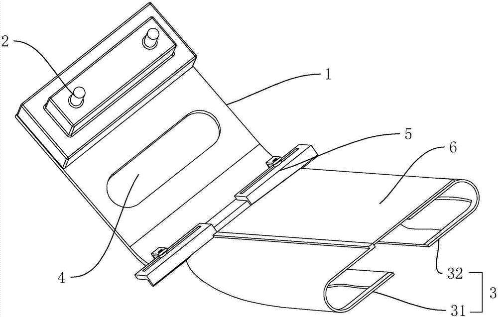
[0038] Example 1: A sticking presser foot, such as figure 1 As shown, it includes a pressing plate with a needle hole 1, a pressing rod 2 and a pulling cylinder 3 arranged on the pressing plate 1. The pressing rod 2 is used to fix the sewing machine to each other, and the pulling cylinder 3 includes a left half 31 and a right half 32 , The left half 31 and the right half 32 are slidably connected to the pressure plate 1 away from or close to each other. The pressure plate 1 is provided with a positioning mechanism 5 for positioning the left half 31 and the right half 32. An extension plate 6 is fixed on the outer wall, and the extension plate 6 extends toward the right half body 32 and is attached to the outer wall of the right half body 32.

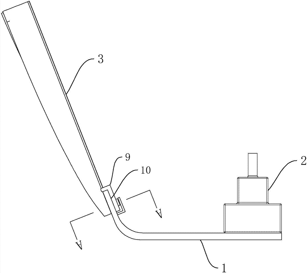
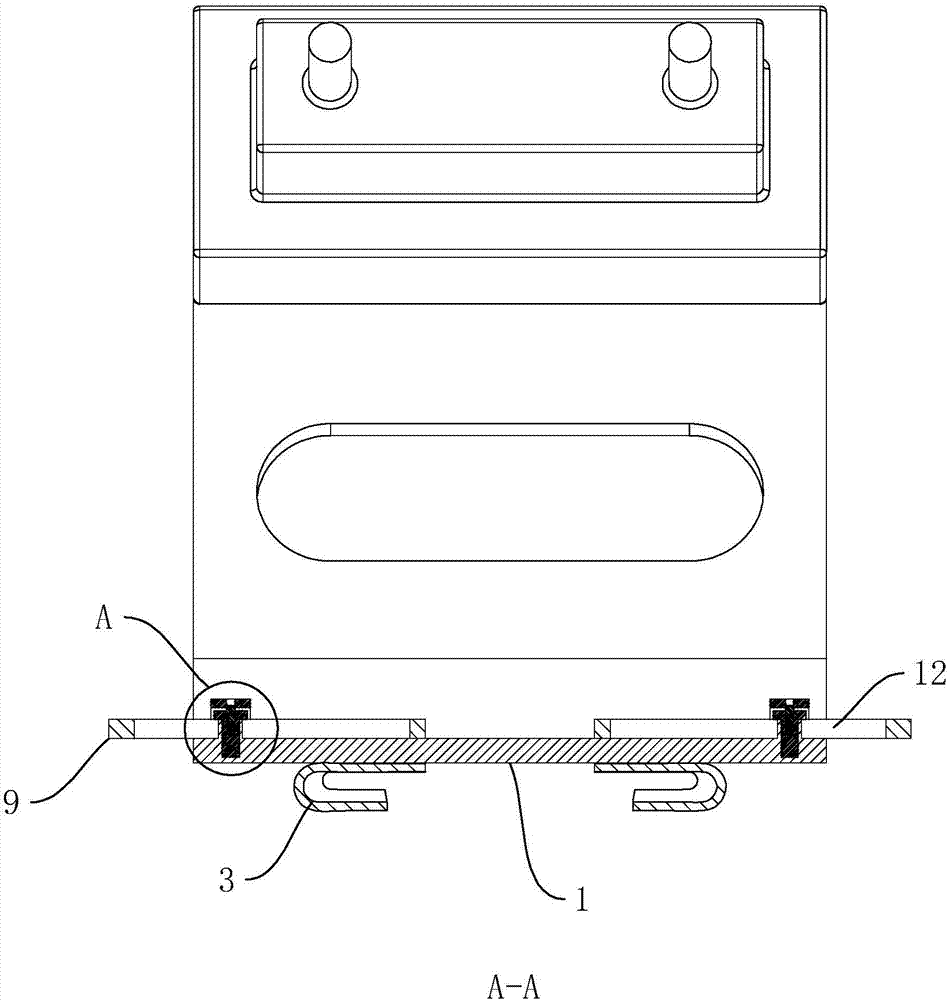
[0039] Such as figure 2 with image 3 As shown, the upper surface of the left half body 31 and the right half body 32 is provided with an "L"-shaped splint 9, and one end of the splint 9 is fixed on the pulling cylinder 3, and a clamp is fo...

Embodiment 2

[0043] Example 2: A sticking foot, such as Image 6 with Figure 7 As shown, the main difference from the first embodiment is that: the pressure plate 1 is provided with a frame 15; the left half 31 and the right half 32 are respectively provided with a slider 14; the frame 15 is provided with a supply slider 14 The sliding groove 13 sliding left and right, the sliding block 14 is slidably arranged in the sliding groove 13; the positioning mechanism 5 includes a double-headed screw 51b and a fixed block 52b. The two ends of the double-headed screw 51b have opposite screw directions, and the fixed block 52b is fixed. On the inner wall of the chute 13, two sliding blocks 14 are respectively located on the left and right sides of the fixed block 52b, the double-headed screw 51b is transversely passed through the fixed block 52b and is rotatably connected with the fixed block 52b. The two ends of the double-headed screw 51b are respectively Passing through the sliders 14 on both sid...

Embodiment 3

[0045] Embodiment 3: A sewing machine, such as Figure 8 As shown, the sticking foot 8 in the first embodiment or the second embodiment is included.

[0046] The same parts are indicated by the same reference numerals. It should be noted that the words "front", "rear", "left", "right", "upper" and "lower" used in the following description refer to the directions in the drawings, and the words "bottom" and "top" "Face", "inner" and "outer" respectively refer to directions toward or away from the geometric center of a particular component.


PUM


Abstract

The invention discloses a sticker pressure foot and a sewing machine with the same, and belongs to sewing devices. The sticker pressure foot comprises a pressure plate, a pressure rod and a folder, the pressure plate and the pressure rod are arranged on the pressure plate, a needle penetrating hole is formed in the pressure plate, the folder comprises a left half body and a right half body, the left half body and the right half body are mutually, remotely or closely and slidably connected on the pressure plate, and a positioning mechanism for positioning the left half body and the right half body is arranged on the pressure plate. The sticker pressure foot can be matched with stickers of a plurality of different widths, and the application range of the pressure foot is widened.

Description

Technical field [0001] The invention relates to a sewing equipment, more specifically, it relates to a sticking presser foot and a sewing machine with the sticking presser foot. Background technique [0002] With the progress of the times, people's demand for clothing styles is becoming more and more diversified. In the design and production, decorative tapes and stickers are often added to the clothing to make the clothing more ornamental. If there is a style of trousers, there are strips at the middle seam of the trousers, making the trousers more personalized. However, in the actual production process, workers need to manually turn up the fabric strips, iron them flat, and sew them on the trousers with a double needle machine. In the manual flanging process, the flanging is prone to problems such as asymmetry, uneven thickness, and uneven edges. In the process of sewing with a double needle machine, it is easy to sew crookedly, which affects the overall effect and product q...

Claims


Application Information

Patent Timeline
Patent Type & Authority Applications(China)
IPC IPC(8): D05B29/06D05B35/06
CPCD05B29/06D05B35/066
Inventor 王利剑
Owner 平湖龙凤时装有限公司
Why Eureka
Try Eureka